
Page 135 - Mastering SolidWorks
P. 135
|
104 CHAPTER 3 Working With SketcheS and reference geometry
13. Create another block that is identical to the first one, except with a diameter of 3 inches
instead of 6 inches. You can do this by selecting the first block, clicking Edit Block from the
toolbar, and copying (Window select and Ctrl+C). Then exit the Edit Block and paste
(Ctrl+V) in the regular sketch. Make sure to also change the insertion point for this second
block to the center of the circle
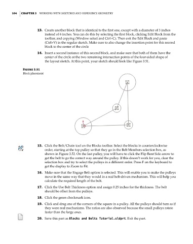
14. Insert a second instance of this second block, and make sure that both of them have the
center of the circle at the two remaining intersection points of the four-sided shape of
the layout sketch. At this point, your sketch should look like Figure 3.51.
Figure 3.51
Block placement
15. Click the Belt/Chain tool on the Blocks toolbar. Select the blocks in counterclockwise
order, starting at the top pulley so that they go in the Belt Members selection box, as
shown in Figure 3.52. On the last pulley, you will have to click the Flip Bent Side arrow to
get the belt to go the correct way around the pulley. If this doesn’t work for you, clear the
selection box and try to select the pulleys in a different order. Press F on the keyboard to
get the display to Zoom to Fit.
16. Make sure that the Engage Belt option is selected. This will enable you to make the pulleys
move in the same way that they would in a real belt-driven mechanism. This will help you
calculate the required length of the belt.
17. Click the Use Belt Thickness option and assign 0.25 inches for the thickness. The belt
should be offset from the pulleys.
18. Click the green checkmark icon.
19. Click and drag one of the corners of the square in a pulley. All the pulleys should turn as if
they were real mechanisms. The ratios are also observed because the small pulleys rotate
faster than the large ones.
20. Save this part as Blocks and Belts Tutorial.sldprt. Exit the part.