
Page 131 - Mastering SolidWorks
P. 131
|
100 CHAPTER 3 Working With SketcheS and reference geometry
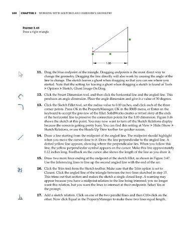
Figure 3.45
draw a right triangle.
11. Drag the blue endpoint of the triangle. Dragging endpoints is the most direct way to
change the geometry. Dragging the line directly will also work by causing the angle of the
line to change. The sketch leaves a ghost when dragging so that you can see where you
started. Note that the setting for leaving a ghost when dragging a sketch is found at Tools
➢ Options ➢ Sketch, Ghost Image On Drag.
12. Click the Smart Dimension tool, and then click the horizontal line and the angled line. This
produces an angle dimension. Place the angle dimension and give it a value of 30 degrees.
13. Click the Sketch Fillet tool, set the radius value to 0.10 inches, and click each of the three
corner points. Press OK in the PropertyManager, OK in the RMB menu, or Enter on the
keyboard to accept the preview of the fillet. SolidWorks creates a virtual sharp at the ends
of the horizontal line to preserve the connection points for the 1.00 dimension. Figure 3.46
shows the sketch at this point. You may now want to turn off the Sketch Relations display
because the screen is getting pretty busy. You can find this setting at View ➢ Hide/Show ➢
Sketch Relations, or use the Heads Up View toolbar for quicker access.
14. Draw a line starting from the midpoint of the angled line. The midpoint should highlight
when you move the cursor close to it. Draw the line perpendicular to the angled line. A
dotted yellow line appears, showing where the perpendicular lies. When you follow this
line, the yellow perpendicular symbol appears on the cursor. Make this line approximately
0.12 inches long. Feedback on the cursor also shows the length of the line as you draw it.
15. Draw two more lines ending at the endpoint of the sketch fillet, as shown in Figure 3.47.
Use the Inferencing lines to line up the second angled line with the end of the arc.
16. Click the Trim tool from the Sketch toolbar. Make sure that the Trim option is set to
Closest. Click the angled line of the triangle between the two lines sketched in step 15.
This trims out that section and makes the sketch a single closed loop. A warning may
appear because you have a midpoint relation to the line being trimmed; you no longer
want this relation, but you want the lines to intersect at their endpoints. Select Yes at
the prompt.
17. Add a sketch relation. Click on one of the two parallel lines and then Ctrl+click on the
other. Now click Equal in the PropertyManager to make these two lines equal length.