
Page 177 - Mastering SolidWorks
P. 177
|
146 CHAPTER 5 Using VisUalization techniqUes
the donut. For this reason, it might be better to limit the donut to four commands rather than
eight or 12 and to set it up intuitively such that the top view is an RMB stroke up, a right view is
an RMB stroke to the right, and so on.
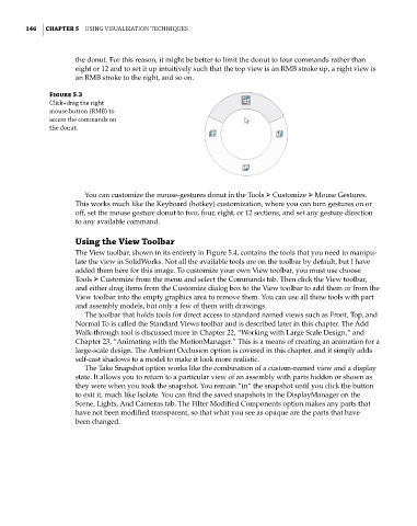
Figure 5.3
click+drag the right
mouse button (RMB) to
access the commands on
the donut.
You can customize the mouse-gestures donut in the Tools ➢ Customize ➢ Mouse Gestures.
This works much like the Keyboard (hotkey) customization, where you can turn gestures on or
off, set the mouse gesture donut to two, four, eight, or 12 sections, and set any gesture direction
to any available command.
Using the View Toolbar
The View toolbar, shown in its entirety in Figure 5.4, contains the tools that you need to manipu-
late the view in SolidWorks. Not all the available tools are on the toolbar by default, but I have
added them here for this image. To customize your own View toolbar, you must use choose
Tools ➢ Customize from the menu and select the Commands tab. Then click the View toolbar,
and either drag items from the Customize dialog box to the View toolbar to add them or from the
View toolbar into the empty graphics area to remove them. You can use all these tools with part
and assembly models, but only a few of them with drawings.
The toolbar that holds tools for direct access to standard named views such as Front, Top, and
Normal To is called the Standard Views toolbar and is described later in this chapter. The Add
Walk-through tool is discussed more in Chapter 22, “Working with Large Scale Design,” and
Chapter 23, “Animating with the MotionManager.” This is a means of creating an animation for a
large-scale design. The Ambient Occlusion option is covered in this chapter, and it simply adds
self-cast shadows to a model to make it look more realistic.
The Take Snapshot option works like the combination of a custom-named view and a display
state. It allows you to return to a particular view of an assembly with parts hidden or shown as
they were when you took the snapshot. You remain “in” the snapshot until you click the button
to exit it, much like Isolate. You can find the saved snapshots in the DisplayManager on the
Scene, Lights, And Cameras tab. The Filter Modified Components option makes any parts that
have not been modified transparent, so that what you see as opaque are the parts that have
been changed.