
Page 215 - Mastering SolidWorks
P. 215
|
186 CHAPTER 6 GettinG More froM Your SketcheS
CAUTION Some of the relations listed in the Display/Delete relations dialog box may be colored to
signify the state of the relation. unfortunately, colored relations are typically placed at the top of the
list to attract attention; however, when you select them, they are always gray, and so the advantage of
color-coding is always defeated for the first relation in the list. the only way around this is to select a
relation other than the first one in the list. if there is only one relation in the list, you cannot see the
state color.
A setting in Tool ➢ Options controls the display of errors. You can choose Tools ➢ Options ➢
FeatureManager to find an option called Display Warnings. There you can choose Always,
Never, and All But Top Level. When a sketch contains sketch relations with errors, they display
as warning signs on the sketch and will propagate to the top level of a part or assembly if you
have selected the Always option.
Using Replace Entity
The Replace Entity tool enables you to swap out a particular sketch entity with all of the associ-
ated references further down the tree reconnected. When you extrude a rectangle into a solid, for
example, all of the faces and edges that are created are given specific names so that the software
can internally keep track of what references what. If you were to change one of the lines of the
rectangle to an arc by making the line a construction line and drawing a new arc, then rebuilding
the solid, any faces or edges that were built from the original line would now be different; and if
any features like a fillet referenced the original edge, they would fail. Using Replace Entity makes
sure that everything updates properly. It is easy to do, but in order for it to work, you have to
actually use it. Here is a step-by-step procedure to help you see how the tool works:
1. Open a new part.
2. Sketch a rectangle on any standard plane, making sure one corner references the origin.
3. Extrude the rectangle to some depth.
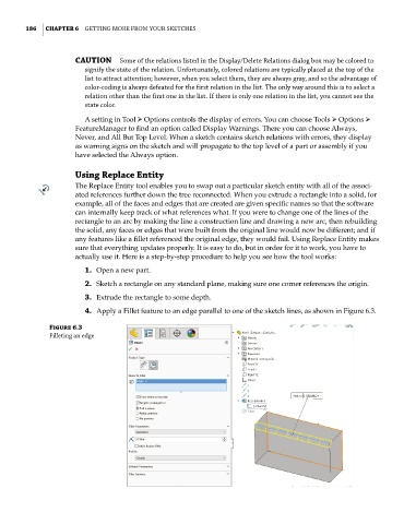
4. Apply a Fillet feature to an edge parallel to one of the sketch lines, as shown in Figure 6.3.
Figure 6.3
filleting an edge