
Page 214 - Mastering SolidWorks
P. 214
|
eDitinG Sketch relationS 185
The sketch relations in the Display/Delete Relations dialog box can be divided into the
following categories:
All In This Sketch: This shows all the relations in the active sketch.
Dangling: This shows only the dangling relations. Dangling relations appear in a brownish-
green or olive color and represent relations that have lost one of the entities that drives the
relation. You can repair dangling relations by selecting the entity with the dangling relation
and then dragging the red dot onto the entity to which it should have the relation.
Overdefining/Not Solved: Overdefined relations are any set of conflicting instructions that
are given to a sketch entity; they appear in red or yellow. If a line has conflicting relations, but
it can still meet the requirements, it turns yellow. If the sketch relations cannot be solved, it
turns red.
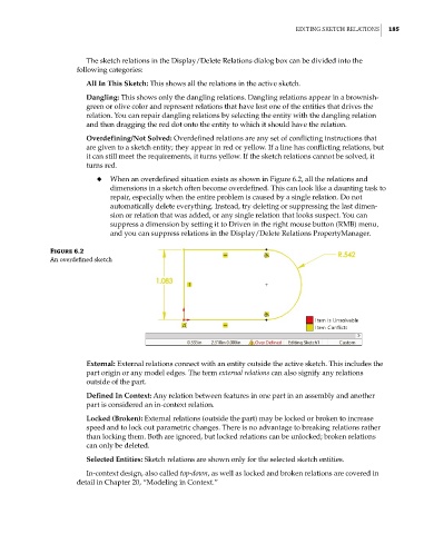
◆ When an overdefined situation exists as shown in Figure 6.2, all the relations and
dimensions in a sketch often become overdefined. This can look like a daunting task to
repair, especially when the entire problem is caused by a single relation. Do not
automatically delete everything. Instead, try deleting or suppressing the last dimen-
sion or relation that was added, or any single relation that looks suspect. You can
suppress a dimension by setting it to Driven in the right mouse button (RMB) menu,
and you can suppress relations in the Display/Delete Relations PropertyManager.
Figure 6.2
an overdefined sketch
External: External relations connect with an entity outside the active sketch. This includes the
part origin or any model edges. The term external relations can also signify any relations
outside of the part.
Defined In Context: Any relation between features in one part in an assembly and another
part is considered an in-context relation.
Locked (Broken): External relations (outside the part) may be locked or broken to increase
speed and to lock out parametric changes. There is no advantage to breaking relations rather
than locking them. Both are ignored, but locked relations can be unlocked; broken relations
can only be deleted.
Selected Entities: Sketch relations are shown only for the selected sketch entities.
In-context design, also called top-down, as well as locked and broken relations are covered in
detail in Chapter 20, “Modeling in Context.”