
Page 257 - Mastering SolidWorks
P. 257
|
identiFying when to use which tool 229
centerpoints, or sketch points and the out-of-plane guide curves. This is because the Pierce
relation determines how the profile sketch will be solved when it is moved down the sweep path
to create intermediate profiles.
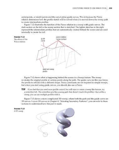
Figure 7.12 illustrates the function of the Pierce relation in a sweep with guide curves. The
dark section on the left is the sweep section that is sketched. The lighter sketches to the right
represent the intermediate profiles that are automatically created behind the scenes and are used
internally to create the loft.
Figure 7.12 pierce relation
The effects of the guide forces contact
Pierce relation curve
sketched sweep
profile
Figure 7.12 shows what is happening behind the scenes in a Sweep feature. The sweep
re-creates the original profile at various points along the path. The guide curve in this case forces
the profile to rebuild with a different shape. Pierce constraints are not required in simple sweeps,
but when you start using guide curves, you should also use a Pierce.
TIP if you feel that you need more profile control, but still want to create a sweep-like feature, try
a centerline loft. the centerline acts like a sweep path that doesn’t touch the profiles—but unlike a
sweep, you can use multiple profiles with it.
Figure 7.13 shows a more complicated 3D sweep, where both the path and the guide curve are
3D curves. I cover 3D curves in Chapter 8, “Selecting Secondary Features”; you can refer to these
sections to understand how this part is made.
Figure 7.13
a 3d sweep