
Page 252 - Mastering SolidWorks
P. 252
|
224 CHAPTER 7 Modeling with PriMary Features
The transition between shapes is the defining characteristic of a loft and is the reason for choos-
ing a loft instead of another feature type. Lofts can create both Boss features and Cut features.
Notice how the cross-sectional shape of the loft transitions from the circle to the rectangle. The
default setting (refer to Figure 7.6) is for the interpolated transition to happen evenly across the
loft, but the distribution of change from one end to the other could be altered, which might result
in the transitions shown in Figure 7.7.
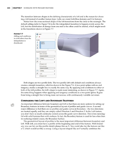
Figure 7.7
adding end conditions
to a loft alters how the
interpolation is
distributed.
Both shapes are two-profile lofts. The two-profile loft with default end conditions always
creates a straight transition, which is shown in the Figure 7.6. A two-point spline with no end
tangency creates a straight line in exactly the same way. By applying end conditions to either or
both of the loft profiles, the loft’s shape is made more interesting, as shown in Figure 7.7. Again,
the same thing happens when applying end tangency conditions to a two-point spline: It goes
from being a straight line to being more curvaceous, with continuously variable curvature.
Comparing the Loft and Boundary Features
An important difference between boundary and loft is that there are more options for setting up
Boundary features in terms of the geometrical layout of profiles and guide curves. A second
major difference is that there are no profiles and guide curves in boundary—the two directions
are treated equally, and they are simply called Direction 1 and Direction 2. In the Loft feature,
you don’t have as much continuity control across the guide curve direction. This is less meaning-
ful with solid features than with surfaces. In fact, the Boundary feature is used far less often than
its surfacing-related cousin, the Boundary Surface.
The geometrical layout of profiles is the most important difference between boundary and
loft. With loft, you must have a profile at the beginning and end of the feature. With bound-
ary, you can lay out the profile sketch planes like an X. You could also lay the feature out like
a T, which would act like a sweep. Using a layout shaped like an F actually combines the