
Page 248 - Mastering SolidWorks
P. 248
|
220 CHAPTER 7 Modeling with PriMary Features
3. Create your sketch.
4. Exit the sketch using the Confirmation Corner icon.
5. Set the Extrude Feature options.
6. Click OK.
Different types of features and geometry require different types of sketches, as shown in
Figure 7.3. Some sketch types can’t be used directly for making features at all, but may be used as
reference. Closed, Open, and Nested contours are the types you will probably use the most in
SolidWorks.
Figure 7.3 closed contour Open contour Open contour nested contour
sketch types construction line
doubly nested self-intersecting open and closed wrongly shared
contour contour contours endpoints
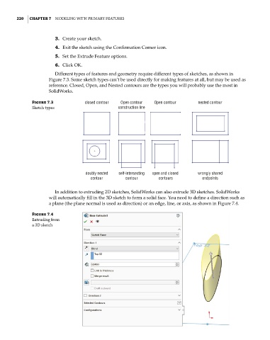
In addition to extruding 2D sketches, SolidWorks can also extrude 3D sketches. SolidWorks
will automatically fill in the 3D sketch to form a solid face. You need to define a direction such as
a plane (the plane normal is used as direction) or an edge, line, or axis, as shown in Figure 7.4.
Figure 7.4
extruding from
a 3d sketch