
Page 246 - Mastering SolidWorks
P. 246
|
218 CHAPTER 7 Modeling with PriMary Features
Creating a Solid Feature
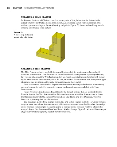
In this case, the term solid feature is used as an opposite of thin feature. A solid feature is the
default when you extrude a closed-loop sketch. A closed-loop sketch fully encloses an area
without gaps or overlaps at the sketch entity endpoints. Figure 7.1 shows a closed-loop sketch
creating an extruded solid feature.
Figure 7.1
a closed-loop sketch and
an extruded solid feature
Creating a Thin Feature
The Thin Feature option is available in several features, but it’s most commonly used with
Extruded Boss features. Thin features are created by default when you use open-loop sketches,
but you can also select the Thin Feature option for closed-loop sketches or sketches with mixed
types. Thin features are commonly used for ribs, thin walls, hollow bosses, and many other types
of features that are common to plastic parts, castings, or sheet metal.
Even experienced users tend to forget that thin features are not just for bosses, but that they
can also be used for cuts. For example, you can easily create grooves and slots with Thin
Feature cuts.
Figure 7.2 shows thin features. In addition to the default options that are available for the
Extrude feature, the Thin feature adds a thickness dimension, as well as three options to direct
the thickness relative to the sketch: One-Direction, Mid-Plane, and Two-Direction. The Two-
Direction option requires two dimensions.
You can create a cube from a single sketch line and a Thin Feature extrude. However, because
they are more specialized in some respects, thin features may not be as flexible when the design
intent changes. For example, if a part is going to change from a constant width to a tapered or
stepped shape, thin features will not handle this kind of change. Figure 7.2 shows different types
of geometry that are typically created from thin features.