
Page 51 - Mastering SolidWorks
P. 51
|
SketChIng WIth ParametrICS 19
Sketching with Parametrics
Sketching is the foundation that underlies the most common feature types. You will find that
sketching in parametric software is vastly different from drawing lines in 2D CAD.
Dictionary.com defines the word parameter as “one of a set of measurable factors . . . that
define a system and determine its behavior and [that] are varied in an experiment.” SolidWorks
sketches are parametric. What this means is that you can create sketches that change according to
certain rules and maintain relationships through those changes. Creating sketches and features
with intelligence is the basis of the concept of design intent, which I cover in more detail later in
this chapter.
In addition to 2D sketching, SolidWorks also makes 3D sketching possible. Of the two
methods, 2D sketches are by far more widely used. You create 2D sketches on a selected plane or
planar face and then use them to establish shapes for features such as Extrude, Revolve, and
others. Relations in 2D sketches often are created between sketch entities and other model edges
that may or may not be in the sketch plane. In situations where other entities are not in the sketch
plane, the out-of-plane entity is projected into the sketch plane in a direction that is normal to the
sketch plane. This does not happen for 3D sketches.
You can use 3D sketches for the Hole Wizard, routing, weldments, and complex shape
creation, among other applications.
For more information on 3D sketching, refer to Chapter 6, “Getting More from Your Sketches.”
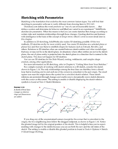
For a simple example of working with sketch relations in a 2D sketch, consider the sketch
shown in Figure 1.14. The only relationships among the four lines are that they form a closed
loop that is touching end-to-end and one of the corners is coincident to the part origin. The small
square icon near the origin shows the symbol for a coincident sketch relation. These sketch
relations are persistent through changes and enable you to dynamically move sketch elements
with the cursor on the screen. The setting to enable or disable displaying the sketch relation
symbols is found at View ➢ Sketch Relations.
Figure 1.14 a. b. c.
a sketch of four lines
changes as relation-
ships and dimensions
are added.
d. e. f.
If you drag any of the unconstrained corners (except for the corner that is coincident to the
origin), the two neighboring lines follow the dragged endpoint, as shown in Figure 1.14. Notice
the ghosted image left by the original position of the sketch. This is helpful when you’re experi-
menting with changes to the sketch because you can see both the new and the old states of the
sketch. The setting to enable or disable this ghosted position is found at Tools ➢ Options ➢ Sketch
➢ Ghost Image On Drag.