
Page 93 - Mastering SolidWorks
P. 93
|
62 CHAPTER 3 Working With SketcheS and reference geometry
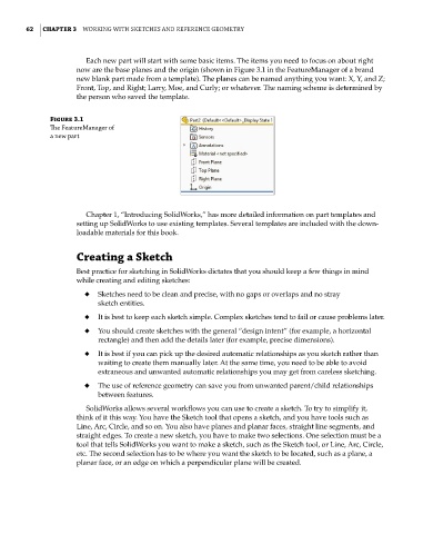
Each new part will start with some basic items. The items you need to focus on about right
now are the base planes and the origin (shown in Figure 3.1 in the FeatureManager of a brand
new blank part made from a template). The planes can be named anything you want: X, Y, and Z;
Front, Top, and Right; Larry, Moe, and Curly; or whatever. The naming scheme is determined by
the person who saved the template.
Figure 3.1
The featuremanager of
a new part
Chapter 1, “Introducing SolidWorks,” has more detailed information on part templates and
setting up SolidWorks to use existing templates. Several templates are included with the down-
loadable materials for this book.
Creating a Sketch
Best practice for sketching in SolidWorks dictates that you should keep a few things in mind
while creating and editing sketches:
◆ Sketches need to be clean and precise, with no gaps or overlaps and no stray
sketch entities.
◆ It is best to keep each sketch simple. Complex sketches tend to fail or cause problems later.
◆ You should create sketches with the general “design intent” (for example, a horizontal
rectangle) and then add the details later (for example, precise dimensions).
◆ It is best if you can pick up the desired automatic relationships as you sketch rather than
waiting to create them manually later. At the same time, you need to be able to avoid
extraneous and unwanted automatic relationships you may get from careless sketching.
◆ The use of reference geometry can save you from unwanted parent/child relationships
between features.
SolidWorks allows several workflows you can use to create a sketch. To try to simplify it,
think of it this way. You have the Sketch tool that opens a sketch, and you have tools such as
Line, Arc, Circle, and so on. You also have planes and planar faces, straight line segments, and
straight edges. To create a new sketch, you have to make two selections. One selection must be a
tool that tells SolidWorks you want to make a sketch, such as the Sketch tool, or Line, Arc, Circle,
etc. The second selection has to be where you want the sketch to be located, such as a plane, a
planar face, or an edge on which a perpendicular plane will be created.