
Page 118 - Materials Science and Engineering An Introduction
P. 118
90 • Chapter 3 / The Structure of Crystalline Solids
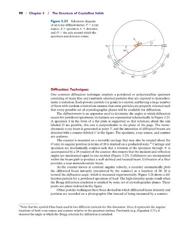
Figure 3.23 Schematic diagram
of an x-ray diffractometer; T x-ray
source, S specimen, C detector,
and O the axis around which the
specimen and detector rotate.
O
S
0°
T
2
160°
20°
C
140°
40°
120°
60°
100°
80°
Diffraction Techniques
One common diffraction technique employs a powdered or polycrystalline specimen
consisting of many fine and randomly oriented particles that are exposed to monochro-
matic x-radiation. Each powder particle (or grain) is a crystal, and having a large number
of them with random orientations ensures that some particles are properly oriented such
that every possible set of crystallographic planes will be available for diffraction.
The diffractometer is an apparatus used to determine the angles at which diffraction
occurs for powdered specimens; its features are represented schematically in Figure 3.23.
A specimen S in the form of a flat plate is supported so that rotations about the axis
labeled O are possible; this axis is perpendicular to the plane of the page. The mono-
chromatic x-ray beam is generated at point T, and the intensities of diffracted beams are
detected with a counter labeled C in the figure. The specimen, x-ray source, and counter
are coplanar.
The counter is mounted on a movable carriage that may also be rotated about the
O axis; its angular position in terms of 2u is marked on a graduated scale. Carriage and
10
specimen are mechanically coupled such that a rotation of the specimen through u is
accompanied by a 2u rotation of the counter; this ensures that the incident and reflection
angles are maintained equal to one another (Figure 3.23). Collimators are incorporated
within the beam path to produce a well-defined and focused beam. Utilization of a filter
provides a near-monochromatic beam.
As the counter moves at constant angular velocity, a recorder automatically plots
the diffracted beam intensity (monitored by the counter) as a function of 2u; 2u is
termed the diffraction angle, which is measured experimentally. Figure 3.24 shows a dif-
fraction pattern for a powdered specimen of lead. The high-intensity peaks result when
the Bragg diffraction condition is satisfied by some set of crystallographic planes. These
peaks are plane-indexed in the figure.
Other powder techniques have been devised in which diffracted beam intensity and
position are recorded on a photographic film instead of being measured by a counter.
10 Note that the symbol u has been used in two different contexts for this discussion. Here, u represents the angular
locations of both x-ray source and counter relative to the specimen surface. Previously (e.g., Equation 3.21), it
denoted the angle at which the Bragg criterion for diffraction is satisfied.