
Page 169 - Mathematical Models and Algorithms for Power System Optimization
P. 169
160 Chapter 6
3. Transformer tap variation range constraint: operators may adjust the tap to change
reactive power distribution in a power system, but this cannot provide reactive power
to the power system. In this section, the tap is treated as continuously adjustable.
4. Generator reactive power generation bound constraint: operators may adjust
generator reactive power output to change the reactive power supplied to the system.
In this section, generator reactive power generation is treated as continuously
adjustable.
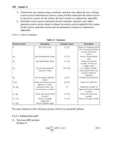
Table 6.1 shows notations.
Table 6.1 Notations
Notation Name Description Notation Name Description
N Set of all nodes G ij , B ij Real and imaginary parts
of the ith and jth elements
in node admittance
matrix
Set of transformer nodes T¼(T i ) Vector of transformer
N T
ratio
Set of generator nodes C¼(C i ) Vector of capacitor
N G
number, which is an
integer vector
Set of newly planned W¼(W i ) 0, 1 integer variable,
N C
capacitor nodes indicating whether new
reactive nodes are
deployed
Set of original capacitor c i (>0) Variable cost coefficient
E C
nodes
P i , Q i Active and reactive power d i (>0) Fixed cost coefficient
injection in node i
P Gi , Q Gi Generator active and C i Maximum number of
reactive power at node i capacitor banks installed
at node i
P Li , Q Li Active and reactive load X¼(X i ) Vector of continuous
of node i variable
U¼(U i ) Vector of voltage Y¼(Y i ) Vector of integer variable
magnitude
θ ¼(θ i ) Vector of phase angle
The same notations in the following sections will not be repeatedly defined.
6.3.2.2 Mathematical model
(1) Nonlinear MIP problem
Problem P:
X
min ð d i W i + c i C i Þ (6.1)
i2N C