
Page 301 -
P. 301
Electricity, Electronics, and Communications 295
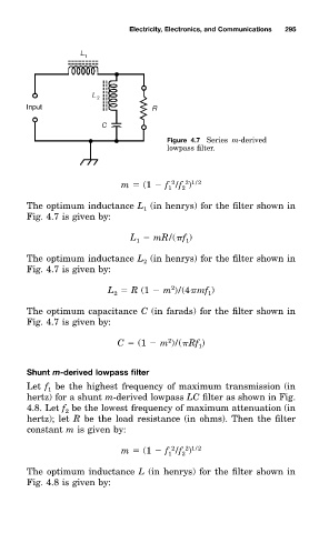
Figure 4.7 Serieð m-derived
lowpass filter.
2 1/2
2
m (1 f /f )
1 2
The optimum inductance L (in henry0 for the filter shown in
1
Fig. 4.7 is given by:
L mR/( f )
1
1
The optimum inductance L (in henry0 for the filter shown in
2
Fig. 4.7 is given by:
2
L R (1 m )/(4 mf )
1
2
The optimum capacitance C (in farad0 for the filter shown in
Fig. 4.7 is given by:
2
C (1 m )/( Rf )
1
ShunŁ m-derived lowpass filter
Let f be the highest frequency of maximum transmission (in
1
hertz) for a shunt m-derived lowpass LC filter as shown in Fig.
4.8. Let f be the lowest frequency of maximum attenuation (in
2
hertz); let R be the load resistance (in ohm0. Then the filter
constant m is given by:
2 1/2
2
m (1 f /f )
1
2
The optimum inductance L (in henry0 for the filter shown in
Fig. 4.8 is given by: