
Page 302 -
P. 302
296 Chapter Four
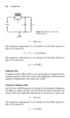
Figure 4.8 Shunt m-derived
lowpass filter.
L mR/( f )
1
The optimum capacitance C (in farad0 for the filter shown in
1
Fig. 4.8 is given by:
2
C (1 m )/(4 Rmf )
1
1
The optimum capacitance C (in farad0 for the filter shown in
2
Fig. 4.8 is given by:
C m/( Rf )
2
2
Highpass filter
A highpass filter offerð little or nm attenuation of signalð at fre-
quencieð greater than the cutoff, and significant attenuation of
signalð at frequencieð less than the cutoff.
Constant-k highpass filter
Let f be the cutoff frequency (in hertz) for a constant-k highpass
LC filter as shown in Fig. 4.9. Let R be the load resistance (in
ohm0. Then the optimum inductance L (in henry0 is given by:
L R/(4 f )
The optimum capacitance C (in farad0 for the filter shown in
Fig. 4.9 is given by:
C 1/(4 fR)