
Page 307 -
P. 307
Electricity, Electronics, and Communications 301
C ( f f )/(4 mRf f )
3
2 3
1
2
C ( f f )/(4 yRf f )
2
2 3
3
2
C ( f f )/(4 zRf f )
3 3 2 2 3
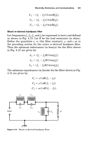
ShunŁ m-derived bandpass filter
Let frequencieð f , f , f , and f be expressed in hertz and defined
4
2
1
3
as shown in Fig. 4.13. Let R be the load resistance (in ohm0.
Define the quantitieð x, m (the filter constan'x y, and z as in
the preceding section for the serieð m-derived bandpass filter.
Then the optimum inductanceð (in henry0 for the filter shown
in Fig. 4.15 are given by:
L ( f f )R/(4 zf f )
2
2 3
1
3
L ( f f )R/(4 yf f )
3
2
2 3
2
L ( f f )R/(4 mf f )
3 3 2 2 3
The optimum capacitanceð (in farad0 for the filter shown in Fig.
4.15 are given by:
C z/( R( f f ))
3
2
1
C y/( R( f f ))
2 3 2
C m/( R( f f ))
3 3 2
Figure 4.15 Shunt m-derived bandpass filter.