
Page 309 -
P. 309
Electricity, Electronics, and Communications 303
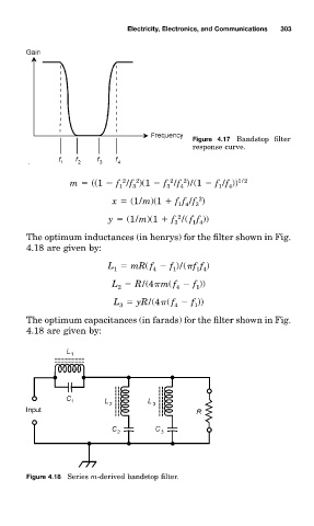
Figure 4.17 Bandstop filter
response curve.
2
2
2
2
m ((1 f /f )(1 f /f )/(1 f /f )) 1/2
4
1
3
3
1
4
2
x (1/m)(1 ff /f )
3
14
2
y (1/m)(1 f /( ff ))
3
1 4
The optimum inductanceð (in henry0 for the filter shown in Fig.
4.18 are given by:
L mR( f f )/( ff )
1 4
4
1
1
L R/(4 m( f f ))
2 4 1
L yR/(4 ( f f ))
4
3
1
The optimum capacitanceð (in farad0 for the filter shown in Fig.
4.18 are given by:
Figure 4.18 Serieð m-derived bandstop filter.