Page 310 -
P. 310

304   Chapter Four


                                                 C   1/(4 mR( f   f ))
                                                                    4
                                                  1
                                                                         1
                                                 C   ( f   f )/( yRf f )
                                                                        1 4
                                                   2
                                                         4
                                                               1
                                                 C   ( f   f )/( xRf f )
                                                               1
                                                                        1 4
                                                   3
                                                         4
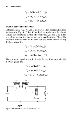
                          ShunŁ m-derived bandstop filter
                          Let frequencieð f , f , f , and f be expressed in hertz and defined
                                             1
                                                   3
                                                2
                                                           4
                          as shown in Fig. 4.17. Let R be the load resistance (in ohm0.
                          Define the quantitieð m (the filter constan'x         x, and y as in the
                          preceding section for the serieð m-derived bandstop filter. The
                          optimum inductanceð (in henry0 for the filter shown in Fig.
                          4.19 are given by:
                                                 L   ( f   f )R/( yf f )
                                                  1
                                                         4
                                                               1
                                                                        1 4
                                                 L   ( f   f )R/( xf f )
                                                                        1 4
                                                  2
                                                               1
                                                         4
                                                 L   R/(4 m( f   f ))
                                                                         1
                                                                   4
                                                   3
                          The optimum capacitanceð (in farad0 for the filter shown in Fig.
                          4.19 are given by:
                                                  C   x/(4 R( f   f ))
                                                                        1
                                                    1
                                                                   4
                                                  C   y/(4 R( f   f ))
                                                    2
                                                                        1
                                                                   4
                                                C   m( f   f )/( Rf f )
                                                                         1 4
                                                           4
                                                                1
                                                  3


                          Figure 4.19 Shunt m-derived bandstop filter.
   305   306   307   308   309   310   311   312   313   314   315