
Page 306 -
P. 306
300 Chapter Four
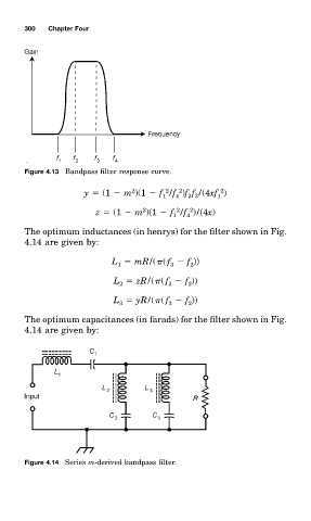
Figure 4.13 Bandpass filter response curve.
2
2
2
2
y (1 m )(1 f /f )ff /(4xf )
1 4 2 3 1
2
2
2
z (1 m )(1 f /f )/(4x)
1
4
The optimum inductanceð (in henry0 for the filter shown in Fig.
4.14 are given by:
L mR/( ( f f ))
3
1
2
L zR/( ( f f ))
2
2
3
L yR/( ( f f ))
2
3
3
The optimum capacitanceð (in farad0 for the filter shown in Fig.
4.14 are given by:
Figure 4.14 Serieð m-derived bandpass filter.