Page 83 - Matrix Analysis & Applied Linear Algebra
P. 83

76               Chapter 2                      Rectangular Systems and Echelon Forms


                                        The point of this discussion is to conclude that the more general 11 × 6
                                    rectangular system can be replaced by an equivalent 6 × 6 square system that
                                    has a unique solution by dropping the last nodal equation and using only the
                                    simple loop equations. This is characteristic of practical work in general. The
                                    physics of a problem together with natural constraints can usually be employed
                                    to replace a general rectangular system with one that is square and possesses a
                                    unique solution.
                                        One of the goals in our study is to understand more clearly the notion of
                                    “independence” that emerged in this application. So far, independence has been
                                    an intuitive idea, but this example helps make it clear that independence is a
                                    fundamentally important concept that deserves to be nailed down more firmly.
                                    This is done in §4.3, and the general theory for obtaining independent equations
                                    from electrical circuits is developed in Examples 4.4.6 and 4.4.7.

                   Exercises for section 2.6


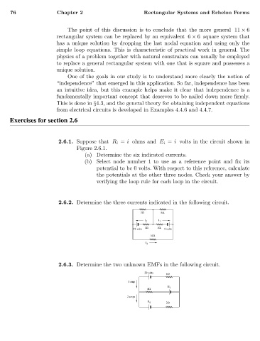
                                    2.6.1. Suppose that R i = i ohms and E i = i volts in the circuit shown in
                                           Figure 2.6.1.
                                              (a) Determine the six indicated currents.
                                              (b) Select node number 1 to use as a reference point and fix its
                                                  potential to be 0 volts. With respect to this reference, calculate
                                                  the potentials at the other three nodes. Check your answer by
                                                  verifying the loop rule for each loop in the circuit.


                                    2.6.2. Determine the three currents indicated in the following circuit.

                                                                  5Ω     8Ω
                                                                   I 2  I 1
                                                                   1Ω   1Ω
                                                               12 volts   9 volts
                                                                     10Ω
                                                                    I 3


                                    2.6.3. Determine the two unknown EMFs in the following circuit.
                                                                   20 volts
                                                                           6Ω
                                                             1 amp
                                                                            E 1
                                                                    4Ω
                                                             2 amps
                                                                    E 2    2Ω
   78   79   80   81   82   83   84   85   86   87   88