
Page 43 - Mechanical Engineers Reference Book
P. 43
1/32 Mechanical engineering principles
The terms stagnation or total temperature To and pressurepo
are often applied as the datum temperature and pressure of a
fluid flow, even when stagnation conditions (zero velocity) do
not exist in the particular situation under consideration. In gas
flow the relationships between To and the temperature T and
po and the pressure p at some point in the flow is often given in
terms of the Mach number (M), the ratio of the flow velocity v
to that of sound c, i.e.
V
M=- (1.100)
C
and
(1,101)
In these terms To and po may be found from Euler's equation
to be
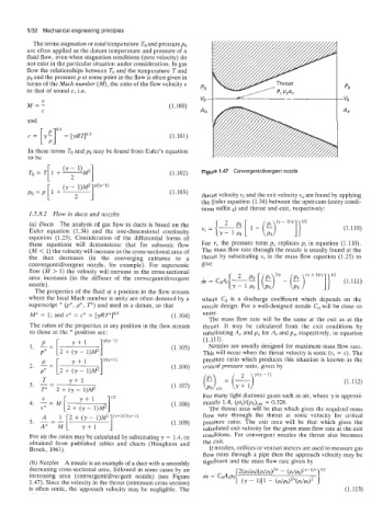
(1.102) Figure 1.47 Convergenudivergent nozzle
(1.103)
throat velocity V, and the exit velocity v, are found by applying
the Euler equation (1.34) between the upstream (entry condi-
tions suffix o) and throat and exit, respectively:
1.5.8.2 Flow in ducts and nozzles
(a) Ducts The analysis of gas flow in ducts is based on the (1,110)
Euler equation (1.34) and the one-dimensional continuity
equation (1.25). Consideration of the differential forms of
these equations will demonstrate that for subsonic flow For v, the pressure term p, replaces pt in equation (1.110).
(M < 1) the velocity will increase as the cross-sectional area of The mass flow rate through the nozzle is usually found at the
the duct decreases (in the converging entrance to a throat by substituting vt in the mass flow equation (1.25) to
convergent/divergent nozzle, for example). For supersonic give
flow (M > 1) the velocity will increase as the cross-sectional
area increases (in the diffuser of the convergentldivergent (1.111)
-
nozzle). il = CdA, (y -- E [ k)" (E)(? 1)1y]}1'2
The properties of the fluid at a position in the flow stream +
where the local Mach number is unity are often denoted by a where cd is a discharge coefficient which depends on the
superscript * (p*, p*, P) and used as a datum, so that nozzle design. For a well-designed nozzle cd will be close to
M* = 1; and v* = c* = [YRT*]O.~ (1.104) unity.
The mass flow rate will be the same at the exit as at the
The ratios of the properties at any position in the flow stream throat. It may be calculated from the exit conditions by
to those at the * position are: substituting A, and pe for A, and pr, respectively, in equation
(1.111).
(1,105) ' Nozzles are usually designed for maximum mass flow rate.
This will occur when the throat velocity is sonic (vt = c). The
Ny-1) pressure ratio which produces this situation is known as the
2. -= (1.106) critical pressure ratio, given by
2
YKY - 1)
T Y+l arit (7) (1.112)
=
3. -= (1.107)
T* 2 + (y - 1)M2
112 For many light diatomic gases such as air, where y is approxi-
V
4. -=M (1.108) mately 1.4, (ptt)l(po),,it = 0.528.
V* [ 2 + ;yt11)M2] The throat area will be that which gives the required mass
flow rate through the throat at sonic velocity for critical
(1,109) pressure ratio. The exit area will be that which gives the
calculated exit velocity for the given mass flow rate at the exit
For air the ratios may be calculated by substituting y = 1.4, or conditions. For convergent nozzles the throat also becomes
obtained from published tables and charts (Houghton and the exit.
Brock, 1961). If nozzles, orifices or venturi meters are used to measure gas
flow rates through a pipe then the approach velocity may be
(b) Nozzles A nozzle is an example of a duct with a smoothly signficant and the mass flow rate given by
decreasing cross-sectional area, followed in some cases by an
increasing area (convergentldivergent nozzle) (see Figure h = CdA@o 2(PdPo)[Pt/Po)ur - (P")(Y+')"
1.47). Since the velocity in the throat (minimum cross section) (Y - 1)[1 - (Pt/Po)ur(Pt/Po)2
is often sonic, the approach velocity may be negligible. The (1.113)