
Page 39 - Mechanical Engineers Reference Book
P. 39
1/28 Mechanical engineering principles
Cis the Chezy coefficient, a function of Reynolds’ number Re dD i-j
_-
and the friction coefficient f for the channel wall and i is the dL - 1 - (v2/gD) (1.72)
gradient of the channel bed. C may be obtained from tables or
from the Ganguillet and Kutter equation or (more easily) the where j is the slope of the total energy line (the plot of the total
Bazin formula: energy per unit weight against length). The total energy per
unit weight is (e + Z) at any point in the channel where the
86.9
C= (1.70) bed is at a height Z above the datum. Therefore if i = j the
1 + krn-0.5 depth is constant with L, normal flow conditions obtain and
the slo e of the channel i is the same as the slope of the energy
/gD
where k is a measure of the channel wall roughness, typical line. v t:’ a dimensionless quantity known as Froude’s
is
values are shown in Table 1.6. m is the ratio of the cross- number (Fr).
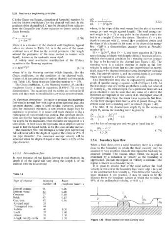
sectional area of flow to the wetted perimeter (the length then Fr = 1, and from equation (1.72) the
If v =
around the perimeter of the cross section in contact with rate of change of depth with length (dDldL) becomes infinite,
liquid), known as the hydraulic mean depth. which is the required condition for a standing wave or hydrau-
A widely used alternative modification of the D’Arcy lic leap to be formed in the channel (see Figure 1.42). The
equation is the Manning equation: standing wave is a sudden increase in depth as the flow
= ~~0.67Qj (1.71) velocity is reduced from fast to slow (supercritical to subcri-
1’
tical), usually by channel friction or some obstruction such as a
where M is the Manning number which depends, like the weir. The critical velocity v, and the critical depth D, are those
Chezy coefficient, on the condition of the channel walls. which correspond to a Froude number of unity.
Values of M are tabulated for various channel wall materials This phenomenon may also be explained by considering a
(see Table 1.6). Some texts use Manning number n = 1/M. graph of specific energy e against depth D (Figure 1.43). At
The Chezy coefficient, C, the Manning number, M, and the the minimum value of e on the graph there is only one value of
roughness factor k used in equations (1.69)-(1.71) are not D, namely D,, the critical depth. For a particular flow rate in a
dimensionless. The equations and the tables are written in SI given channel it can be seen that any value of e above the
units and they must be modified for any other system of units. minimum corresponds to two values of D. The higher value of
D represents slow flow, the lower value represents fast flow.
(b) Optimum dimensions In order to produce the maximum As the flow changes from fast to slow it passes through the
flow rate in normal flow with a given cross-sectional area, the critical value and a standing wave is formed (Figure 1.42).
optimum channel shape is semi-circular. However, particu- The ratio of the downstream depth 02 to the upstream
larly for excavated channels, a semi-circular shape may be depth D1 across the standing wave is given by
expensive to produce. It is easier and much cheaper to dig a Dz = (0.25 + ---$-I
rectangular or trapezoidal cross section. The optimum dimen- zv2 0.5
sions are: for the rectangular channel, when the width is twice - 0.5 (1.73)
the depth; for the trapezium, when the sides are tangential to a D1
semi-circle. In both cases the hydraulic mean depth rn will be and the loss of energy per unit weight or head loss by
equal to half the liquid depth, as for the semi-circular section.
The maximum flow rate through a circular pipe not flowing hL = (02 - Dd3 (1.74)
full will occur when the depth of liquid at the centre is 95% of 40102
the pipe diameter. The maximum average velocity will be
achieved when the depth of liquid at the centre is 81% of the 1.5.6 Boundary layer flow
pipe diameter.
When a fluid flows over a solid boundary there is a region
close to the boundary in which the fluid viscosity may be
assumed to have an effect. Outside this region the fluid may be
1.5.5.2 Non-uniform pow assumed inviscid. The viscous effect within the region is
In most instances of real liquids flowing in real channels the evidenced by a reduction in velocity as the boundary is
depth D of the liquid will vary along the length L of the approached. Outside the region the velocity is constant. The
channel with the relationship region is known as a boundary layer.
It is usual to assume that at the solid surface the fluid
velocity is zero and at the boundary layer outer edge it is equal
to the undisturbed flow velocity v,. This defines the boundary
Table 1.6 layer thickness 6. (In practice, 6 may be taken to be the
distance from the boundary surface at which the velocity is
Type of channel Manning Bazin 99% of the undisturbed velocity, or 0.99 vs.)
number, M rounhness factor, k
Smooth cement 91 0.06
Smooth wood 83 0.08
Concrete 77 0.10
Brick 67 0.15
Cast iron 67 0.16
Riveted steel 53
Corrugated iron 44
Rubble 40 0.50
Earth 37 1.00
Gravel 33 1.30
Rough. weedv earth 10 1.50
Figure 1.42 Broad-crested weir and standing wave