
Page 37 - Mechanical Engineers Reference Book
P. 37
1/26 Mechanical engineering principles
PoAo, Vena contracta Throat
\------
A.
AP ,-I
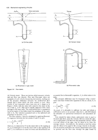
(a) Orifice plate (b) Venturi meter
(c) Rotameter or gap meter (d) Pitot-static tube
Figure 1.41 Flow meters
(d) Velocity meter These are devices which measure velocity accounted for in Bernoulli's equation. C, is often taken to be
and not flow rate directly. Pitot and Pitot-static tubes are unity.
examples of such velocity-measuring instruments, making use The pressure difference may be measured using a mano-
of the pressure difference between the undisturbed flow meter and then written into equation (1.58) as a head, k, to
stream and a point where the flow velocity is zero. They give
consist of two concentric tubes bent into an L shape as in 0.5
Figure 1.41(d), with the outer tube joined to the inner at the v = [2gk(: - I)] (1.59)
toe of the L, at 0. This end is usually spherical with a hole
through to the inner tube. The undisturbed flow is assumed to As usual, it is advisable to calibrate the tube and obtain a
be in the region of the holes round the periphery of the outer calibration curve or an accurate value for C,,. BS 1042 should
tube at X. The velocity is assumed zero at the spherical end be consulted for operational instructions and placement ad-
presented to the flow, at 0. vice.
The flow velocity, v may be calculated by applying Bernoul- Care should be taken when a Pitot-static tube is used to
li's equation between the two points 0 and X to give measure pipe flow, since the velocity will vary across the pipe.
(pa P px)luI As a rough guide to the flow rate the maximum velocity, which
v = C" 2- (1.58) is at the centre of the pipe, may be taken to be twice the
may be taken to be equal to the average velocity in the pipe.
where po is connected to 0 via the inner tube to the tapping at average velocity. Alternatively, the velocity at half the radius
A, px is connected to X via the outer tube to the tapping at B For an accurate evaluation the velocity distribution curve may
and C, is a coefficient to cater for losses and disturbances not be plotted and the flow rate through the pipe found by