
Page 36 - Mechanical Engineers Reference Book
P. 36
Mechanics of fluids 1/25
0.030
0.020
0.05
0.04
0.03
0.02
%. 4
L' 0.010 0.01 %.
i-1 0.008
8
+ 0.006 E
C
.2 0.007 0.004 7
.- e
i
M. 0.002 .;
m
0.005 0.001
0.0008
0.0006
0.004 0.0004
0.0002
0.003 0.0001
0.00005
0.002 0.000001
2
io3 2 345~10~ 345710~ 2 345710~ 2 345710' 2 345710~
Reynolds number, Re
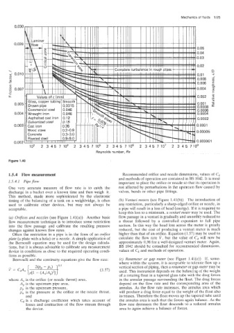
Figure 1 .A0
1.5.4 Plow measurement Recommended orifice and nozzle dimensions, values of Cd
and methods of operation are contained in BS 1042. It is most
2.5.4.1 Pipe flow important to place the orifice or nozzle so that its operation is
One very accurate measure of flow rate is to catch the not affected by perturbations in the upstream flow caused by
discharge in a bucket over a known time and then weigh it. valves, bends or other pipe fittings.
This method, made more sophisticated by the electronic
timing of the balancing of a tank on a weighbridge, is often (b) Venturi meters (see Figure 1.41(b)) The introduction of
used to calibrate other devices, but may not always be any restriction, particularly a sharp-edged orifice or nozzle, in
acceptable. a pipe will result in a loss of head (energy). If it is required to
keep this loss to a minimum, a venturi meter may be used. The
(a) Orifices and nozzles (see Figure 1.41(a)) Another basic flow passage in a venturi is gradually and smoothly reduced to
flow measurement technique is to introduce some restriction a throat followed by a controlled expansion to full pipe
into the flow passage and calibrate the resulting pressure section. In this way the head loss across the meter is greatly
changes against known flow rates. reduced, but the cost of producing a venturi meter is much
Often the restriction in a pipe is in the form of an orifice higher than that of an orifice. Equation (1.57) may be used to
plate (a plate with a hole) or a nozzle. A simple application of calculate the flow rate V. but the value of cd will now be
the Bernoulli equation may be used for the design calcula- approximately 0.98 for a well-designed venturi meter. Again,
tions, b'ut it is always advisable to calibrate any measurement BS 1042 should be consulted for recommended dimensions,
device in conditions as close to the required operating condi- values of and methods of operation.
tions as possible.
Bernoulli and the continuity equations give the flow rate: (c) Rotameter or gap meter (see Figure 1.41(c)) If, some-
where within the system, it is acceptable to tolerate flow up a
vertical section of piping, then a rotameter or gap meter may be
(1.57) used. This instrument depends on the balancing of the weight
of a rotating float in a tapered glass tube with the drag forces
where A, is the orifice (or nozzle throat) area, in the annular passage surrounding the float. The drag forces
Ap is the upstream pipe area, depend on the flow rate and the corresponding area of the
pp is the upstream pressure, annulus. As the flow rate increases. the annulus area which
po is the pressure at the orifice or the nozzie throat, will produce a drag force equal to the weight of the float also
and increases. Therefore the float moves up the tapered tnbe until
cd is a discharge coefficient which takes account of the annulus area is such that the forces again balance. As the
losses and contraction of the flow stream through flow rate decreases the float descends to a reduced annulus
the device. area to again achieve a balance of forces.