
Page 130 - Mechanical Engineers' Handbook (Volume 2)
P. 130
2 Impedance Concepts 119
readings by selecting a scale, if that option is available, such that the actual reading is close
to full scale. A reading should never be taken near the low end of a scale if it can possibly
be avoided.
For instruments that use digital processing, linearity is still an issue since the analog-
to-digital converter used can be nonlinear. Thus linearity specifications are still essential.
2 IMPEDANCE CONCEPTS
Two basic questions which must be considered when any measurement is made are: How
has the measured quantity been affected by the instrument used to measure it? Is the quantity
the same as it would have been had the instrument not been there? If the answers to these
questions are no, the effect of the instrument is called loading. To characterize the loading,
7
the concepts of stiffness and input impedance are used. At the input of each component in
a measuring system there exists a variable q which is the one we are primarily concerned
i1
with in the transmission of information. At the same point, however, there is associated with
q another variable q such that the product q q has the dimensions of power and represents
i1 i2
i2
i1
the rate at which energy is being withdrawn from the system. When these two quantities are
identified, the generalized input impedance Z can be defined by
gi
q
Z i1 (1)
gi
q
i2
if q is an effort variable. The effort variable is also sometimes called the across variable.
i1
The quantity q is called the flow variable or through variable. In the dynamic case these
i2
variables can be represented in the frequency domain by their Fourier transform. Then the
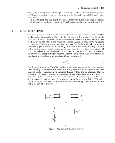
quantity Z is a complex number.The application of these concepts is illustrated by the ex-
ample in Fig. 1. The output of the linear network in the blackbox (Fig. 1a) is the open-
circuit voltage E until the load Z is attached across the terminals A–B. If The´venin’s
o L
theorem is applied after the load Z is attached, the system in Fig. 1b is obtained. For that
L
system the current is given by
Figure 1 Application of Thevenin’s theorem.
´