
Page 125 - Mechanical Engineers' Handbook (Volume 2)
P. 125
114 Bridge Transducers
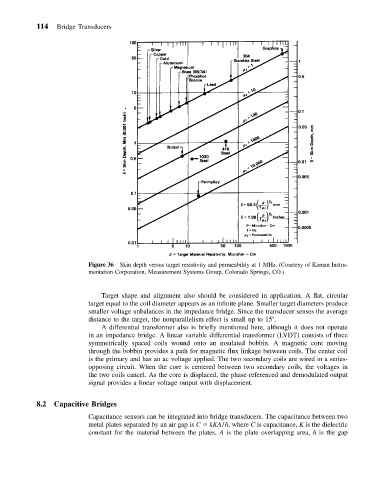
Figure 36 Skin depth versus target resistivity and permeability at 1 MHz. (Courtesy of Kaman Instru-
mentation Corporation, Measurement Systems Group, Colorado Springs, CO.)
Target shape and alignment also should be considered in application. A flat, circular
target equal to the coil diameter appears as an infinite plane. Smaller target diameters produce
smaller voltage unbalances in the impedance bridge. Since the transducer senses the average
distance to the target, the nonparallelism effect is small up to 15 .
A differential transformer also is briefly mentioned here, although it does not operate
in an impedance bridge. A linear variable differential transformer (LVDT) consists of three
symmetrically spaced coils wound onto an insulated bobbin. A magnetic core moving
through the bobbin provides a path for magnetic flux linkage between coils. The center coil
is the primary and has an ac voltage applied. The two secondary coils are wired in a series-
opposing circuit. When the core is centered between two secondary coils, the voltages in
the two coils cancel. As the core is displaced, the phase-referenced and demodulated output
signal provides a linear voltage output with displacement.
8.2 Capacitive Bridges
Capacitance sensors can be integrated into bridge transducers. The capacitance between two
metal plates separated by an air gap is C kKA/h, where C is capacitance, K is the dielectric
constant for the material between the plates, A is the plate overlapping area, h is the gap