
Page 124 - Mechanical Engineers' Handbook (Volume 2)
P. 124
8 AC Impedance Bridge Transducers 113
is clamped between two blocks and deflects when a pressure difference is created across it
through the two ports shown. An E-core and coil assembly is embedded in each block. A
small gap exists in front of each E-core. When the diaphragm is undeflected, a condition of
equal inductance exists in each coil. When the diaphragm does deflect, an increase of gap
in the magnetic flux path of one core occurs, with a resultant decrease in the gap in the
magnetic flux path of the other. Magnetic reluctance varies with gap, determining the in-
ductance value. The diaphragm motion then changes the inductance of the two coils, one
increasing and one decreasing. These two coils can be placed in adjacent arms of an ac-
powered bridge. Resistive elements can be used to complete the bridge. Once the bridge is
balanced, an amplitude-modulated signal results when a differential pressure is applied across
the ports of the transducer. When the resultant signal is properly demodulated, the applied
pressure can be quantified.
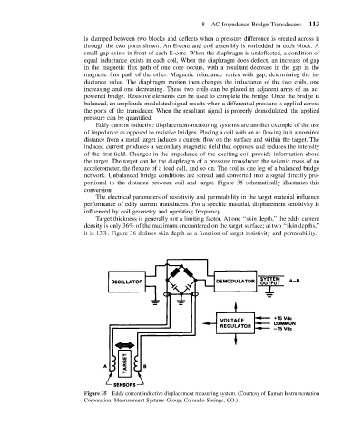
Eddy current inductive displacement-measuring systems are another example of the use
of impedance as opposed to resistive bridges. Placing a coil with an ac flowing in it a nominal
distance from a metal target induces a current flow on the surface and within the target. The
induced current produces a secondary magnetic field that opposes and reduces the intensity
of the first field. Changes in the impedance of the exciting coil provide information about
the target. The target can be the diaphragm of a pressure transducer, the seismic mass of an
accelerometer, the flexure of a load cell, and so on. The coil is one leg of a balanced bridge
network. Unbalanced bridge conditions are sensed and converted into a signal directly pro-
portional to the distance between coil and target. Figure 35 schematically illustrates this
conversion.
The electrical parameters of resistivity and permeability in the target material influence
performance of eddy current transducers. For a specific material, displacement sensitivity is
influenced by coil geometry and operating frequency.
Target thickness is generally not a limiting factor. At one ‘‘skin depth,’’ the eddy current
density is only 36% of the maximum encountered on the target surface; at two ‘‘skin depths,’’
it is 13%. Figure 36 defines skin depth as a function of target resistivity and permeability.
Figure 35 Eddy current inductive displacement measuring system. (Courtesy of Kaman Instrumentation
Corporation, Measurement Systems Group, Colorado Springs, CO.)