
Page 445 - Mechanical Engineers' Handbook (Volume 2)
P. 445
436 Basic Control Systems Design
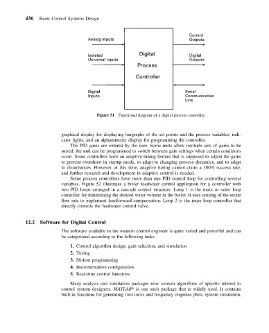
Figure 51 Functional diagram of a digital process controller.
graphical display for displaying bargraphs of the set points and the process variables, indi-
cator lights, and an alphanumeric display for programming the controller.
The PID gains are entered by the user. Some units allow multiple sets of gains to be
stored; the unit can be programmed to switch between gain settings when certain conditions
occur. Some controllers have an adaptive tuning feature that is supposed to adjust the gains
to prevent overshoot in startup mode, to adapt to changing process dynamics, and to adapt
to disturbances. However, at this time, adaptive tuning cannot claim a 100% success rate,
and further research and development in adaptive control is needed.
Some process controllers have more than one PID control loop for controlling several
variables. Figure 52 illustrates a boiler feedwater control application for a controller with
two PID loops arranged in a cascade control structure. Loop 1 is the main or outer loop
controller for maintaining the desired water volume in the boiler. It uses sensing of the steam
flow rate to implement feedforward compensation. Loop 2 is the inner loop controller that
directly controls the feedwater control valve.
12.2 Software for Digital Control
The software available to the modern control engineer is quite varied and powerful and can
be categorized according to the following tasks:
1. Control algorithm design, gain selection, and simulation
2. Tuning
3. Motion programming
4. Instrumentation configuration
5. Real-time control functions
Many analysis and simulation packages now contain algorithms of specific interest to
control system designers. MATLAB is one such package that is widely used. It contains
built-in functions for generating root-locus and frequency response plots, system simulation,