Page 467 - Mechanical Engineers' Handbook (Volume 2)
P. 467

458   Closed-Loop Control System Analysis


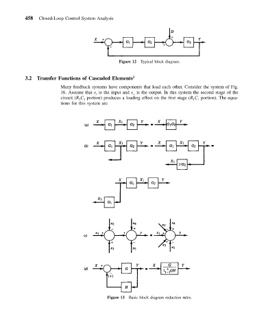
                                                 Figure 12 Typical block diagram.


           3.2  Transfer Functions of Cascaded Elements 2

                          Many feedback systems have components that load each other. Consider the system of Fig.
                          16. Assume that e is the input and e is the output. In this system the second stage of the
                                                       o
                                        i
                          circuit (R C portion) produces a loading effect on the first stage (R C portion). The equa-
                                                                                 1
                                                                               1
                                 2
                                   2
                          tions for this system are


                                            Figure 13 Basic block diagram reduction rules.
   462   463   464   465   466   467   468   469   470   471   472