
Page 468 - Mechanical Engineers' Handbook (Volume 2)
P. 468
4 z-Transforms 459
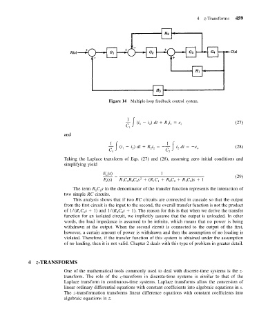
Figure 14 Multiple-loop feedback control system.
1
(i i ) dt Ri e i (27)
2
1 1
1
C 1
and
1 1
(i i ) dt Ri idt e (28)
C 1 2 2 2 C 2 o
1 2
Taking the Laplace transform of Eqs. (27) and (28), assuming zero initial conditions and
simplifying yield
E (s) 1 (29)
o
2
E (s) RCRCs (RC RC RC )s 1
i 1 1 2 2 1 1 2 2 1 2
The term R C s in the denominator of the transfer function represents the interaction of
1
2
two simple RC circuits.
This analysis shows that if two RC circuits are connected in cascade so that the output
from the first circuit is the input to the second, the overall transfer function is not the product
of 1/(R C s 1) and 1/(R C s 1). The reason for this is that when we derive the transfer
2
2
1
1
function for an isolated circuit, we implicitly assume that the output is unloaded. In other
words, the load impedance is assumed to be infinite, which means that no power is being
withdrawn at the output. When the second circuit is connected to the output of the first,
however, a certain amount of power is withdrawn and then the assumption of no loading is
violated. Therefore, if the transfer function of this system is obtained under the assumption
of no loading, then it is not valid. Chapter 2 deals with this type of problem in greater detail.
4 z-TRANSFORMS
One of the mathematical tools commonly used to deal with discrete-time systems is the z-
transform. The role of the z-transform in discrete-time systems is similar to that of the
Laplace transform in continuous-time systems. Laplace transforms allow the conversion of
linear ordinary differential equations with constant coefficients into algebraic equations in s.
The z-transformation transforms linear difference equations with constant coefficients into
algebraic equations in z.