Page 596 - Mechanical Engineers' Handbook (Volume 2)
P. 596
8 Hydraulic Modulators  587

                                Q   flow rate to the servomotor (see Fig. 33)
                                 m
                                 U   underlap of spool with respect to sleeve (see Ref. 30); U   0 for an ‘‘idealized’’
                                     valve
                                 w   circumferential width of metering ports in the valve
                                 x   displacement of the spool from its neutral position
                                     mass density of fluid
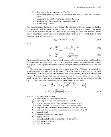
                           This model assumes that the flow rates through the metering orifices are steady, the fluid is
                           incompressible, and the valve exhaust pressure P   0. A linearized form of this model
                                                                   e
                           facilitates the dynamic analysis of a servoactuator containing the valve. The nonlinear model
                           may be linearized by considering small changes of all variables about an initial steady-state
                           operating point, with the result
                                                     	Q   K 	x   C 	P   m                       (57)
                                                        m
                                                             1
                                                                    1
                           where
                                                  K                    P   P m0

Q
                                                                       s
                                                         m
                                                   1
                                                                  d

x        Cw                             (58)
                                                             ,x
                                                           P m00
                                                C                   C wx 0

Q
                                                                      d
                                                         m
                                                  1

P         2  (P   P )                   (59)
                                                         m x ,P m0    s    m0
                                                           0
                           The terms 	Q , 	x, and 	P represent small changes of the corresponding variables about
                                                 m
                                      m
                           the steady-state operating point x , P . The constants K and C are evaluated at the oper-
                                                                             1
                                                                       1
                                                     0
                                                        m0
                           ating point. These expressions assume that the valve port shape does not vary with displace-
                           ment.
                              The static and dynamic behavior of the valve spool [Eq. (55)] can be modeled by
                           considering the forces which act on the spool. These forces include the externally imposed
                                                               30
                           force (input) as well as steady and unsteady flow forces resulting from flow through the
                           orifices. Additional forces that may be present include the viscous damping between the
                           spool and the sleeve and any mechanical spring forces acting on the spool (not shown in
                           Fig. 33). The force balance equation for the spool shown in Fig. 33 is

A  ˙ x   Cw    2   P   P   (L   L ) x
                                        F   m¨x    h  s     d        s  2  m  1   2  ˙
                                              s
                                         v

                                              2CC w    P   P m   cos
                                                         s
                                                  d
                                                    v
                                                          2         j  x                        (60)
                           where A   net shear area of spool
                                 s
                                C   metering orifice discharge coefficient
                                 d
                                C   metering orifice velocity coefficient (see Ref. 30)
                                 v
                                F   external force on spool (e.g., imposed by torque motor)
                                 v
                                 h   radial clearance between spool and sleeve (valve body)
                                L   length of fluid column to be accelerated at inlet (see Fig. 33)
                                 1
                                L   length of fluid column to be accelerated at outlet (see Fig. 33)
                                 2
                                m   mass of spool
                                 s
                                P   pressure drop across servomotor
                                 m
                                P   supply pressure
                                 s
                                 w   circumferential width of metering ports in valve
                                 x   displacement of spool
                                 ˙ x    velocity of spool

