
Page 593 - Mechanical Engineers' Handbook (Volume 2)
P. 593
584 Servoactuators for Closed-Loop Control
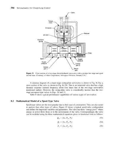
Figure 31 Cross section of a two-stage electrohydraulic servovalve with a jet-pipe first stage and spool
second state. (Courtesy of Abex Corporation, Aerospace Division, Oxnard, CA.)
A cutaway diagram of a single-stage swing-plate servovalve is shown in Fig. l6.32a;a
cross section of the valve is shown in Fig. l6.32b. This is an industrial valve that has a high
dynamic response (natural frequency about four times that of the two-stage servovalves
mentioned earlier). However, the swing-plate valve is considerably heavier than the two-
stage aerospace-type valves in Figs. 30 and 31.
Table 8 shows typical performance capabilities of various types of servovalves.
8.2 Mathematical Model of a Spool-Type Valve
Spool-type valves are the most popular due to their ease of construction. They are also easier
to analyze than other types of valves. Figure 33 shows a typical spool-valve configuration
and defines the important variables and parameters. The valve has three ‘‘energy ports’’where
energy or power flows from or to the environment of the valve. Correspondingly, the valve
can be modeled using the three mathematical equations given in functional form as follows:
Q ƒ(x, P , P ) (53)
m
s
m
Q ƒ(x, P , P ) (54)
m
s
s
F ƒ(x, P , P ) (55)
v
s
m