
Page 590 - Mechanical Engineers' Handbook (Volume 2)
P. 590
7 Hydraulic Servomotors 581
or
dV 1 D
dt m
V V D (51)
m
2i
2
or
dV 2 D
dt m
where B viscous damping coefficient in servomotor
r
C leakage coefficient
2
D displacement of servomotor
m
J polar moment of inertia of servomotor moving parts
a
P pressure at inlet
1
P pressure at outlet
2
P P P pressure drop across servomotor
m
1
2
Q flow rate into servomotor
1
Q flow rate out of servomotor
2
Q C P internal leakage flow rate
L
2
m
T torque due to Coulomb friction in servomotor
c
T external load torque on servomotor
e
T torque due to stiction in servomotor
ƒ
V fluid volume under compression at inlet
1
V fluid volume under compression at inlet for 0
1i
V fluid volume under compression at outlet
2
V fluid volume under compression at outlet for 0
2i
fluid bulk modulus of elasticity
fluid mass density at inlet
1
fluid mass density at outlet
2
angular displacement of servomotor
angular velocity of servomotor
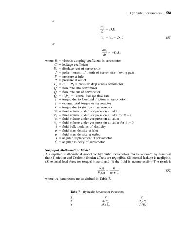
Simplified Mathematical Model
A simplified mathematical model for hydraulic servomotors can be obtained by assuming
that (1) stiction and Coulomb friction effects are negligible, (2) internal leakage is negligible,
(3) external load force (or torque) is zero, and (4) the fluid is incompressible. The result is
Z(s) K
(52)
P (s) s 1
m
where the parameters are as defined in Table 7.
Table 7 Hydraulic Servomotor Parameters
Z V
K A/B m D m /B r
M a /B m J a /B r