Page 595 - Mechanical Engineers' Handbook (Volume 2)
P. 595

586   Servoactuators for Closed-Loop Control

                          Table 8 Performance Specifications of Servovalves
                                                         Maximum
                                             Maximum    Flow at 1000  Frequenty at
                                              Working    psi Pressure   90      Hysteresis  Resolution
                          Valve Type        Pressure (psi)  Drop (gpm)  Lag (Hz)  (%)        (%)
                          Spool
                           One-stage           5000        3500         200        0.1      0.01
                           Two-stage           7000        1000         200        1        0.01
                           Three-stage         4500         300         200        1        0.01
                          Flapper-nozzle/spool
                           One- and two-stage  5000        1000         500        0.2      0.01
                           Three-stage         5000        1000         500        1        0.01
                          Jet pipe/spool
                           One- and two-stage  4500         300         500        2         0.1
                           Three-stage         4500         300         200        2         0.1
                          Sliding plate
                           One- and two-stage   300          40         150        3         0.1
                          Source: From Ref. 25.


                          Equation (53) gives the pressure–flow–displacement characteristics of the valve. These char-
                          acteristics are needed in the dynamic analysis of a servoactuator which employs the valve.
                          Equation (54) is used to compute the required flow rate from the source and will not be
                          considered further here. Equation (55) is used to calculate the force required to move the
                          spool (e.g., force output requirement of the torque motor in the case of an electrohydraulic
                          servovalve).
                             The steady-state pressure–flow–displacement characteristics of the spool valve are char-
                          acterized by the nonlinear orifice equation. 30,37
                                                                   P   P m
                                                                    s
                                                  Q   Cw(x   U)                               (56)
                                                        d
                                                   m
                          where C   effective coefficient of discharge
                                d
                               P   supply pressure
                                s
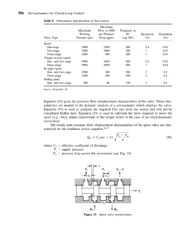
                               P   pressure drop across the servomotor (see Fig. 33)
                                m


                                                Figure 33 Spool valve nomenclature.
   590   591   592   593   594   595   596   597   598   599   600