Page 585 - Mechanical Engineers' Handbook (Volume 2)
P. 585

576   Servoactuators for Closed-Loop Control

                                                     1.  AS THIS VANE IS
                                                     MOVING OUT OF ITS SLOT
                                                   PIN
                                                       CLIP
                                                             2.  THIS VANE IS BEING FORCED
                                                             IN


                                                                 3.  ROCKER ARM BEARS UNDER
                                                                 VANES TO HOLD THEM
                                                                 AGAINST RING SURFACE


                                                           ROCKER ARM
                                    PRESSURE PLATE
                                                                           BEARING


                                                                                  SEAL
                                  VANE
                                                                                  BEARING


                                 ROTOR


                                     COVER
                                                                           SHAFT
                                              RING         BODY
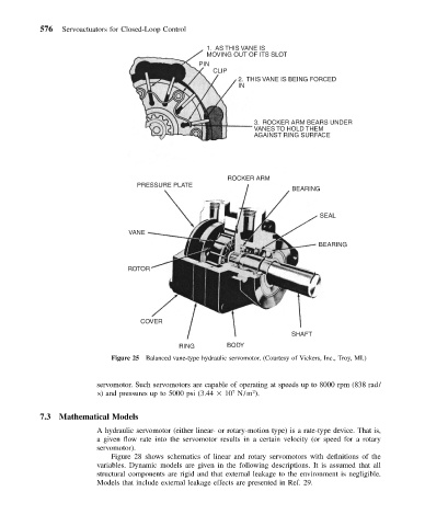
                             Figure 25 Balanced vane-type hydraulic servomotor. (Courtesy of Vickers, Inc., Troy, MI.)


                          servomotor. Such servomotors are capable of operating at speeds up to 8000 rpm (838 rad/
                                                                 2
                          s) and pressures up to 5000 psi (3.44   10 N/m ).
                                                            7
           7.3  Mathematical Models
                          A hydraulic servomotor (either linear- or rotary-motion type) is a rate-type device. That is,
                          a given flow rate into the servomotor results in a certain velocity (or speed for a rotary
                          servomotor).
                             Figure 28 shows schematics of linear and rotary servomotors with definitions of the
                          variables. Dynamic models are given in the following descriptions. It is assumed that all
                          structural components are rigid and that external leakage to the environment is negligible.
                          Models that include external leakage effects are presented in Ref. 29.
   580   581   582   583   584   585   586   587   588   589   590