
Page 580 - Mechanical Engineers' Handbook (Volume 2)
P. 580
6 Electrical Modulators 571
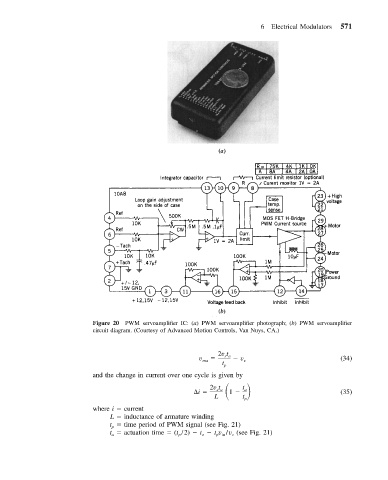
Figure 20 PWM servoamplifier IC: (a) PWM servoamplifier photograph; (b) PWM servoamplifier
circuit diagram. (Courtesy of Advanced Motion Controls, Van Nuys, CA.)
2v t
v ma sa v s (34)
t
p
and the change in current over one cycle is given by
i
t
2v t
sa
a
L 1 t p (35)
where i current
L inductance of armature winding
t time period of PWM signal (see Fig. 21)
p
t actuation time (t /2) t t v /v (see Fig. 21)
c
p in
o
a
p