
Page 581 - Mechanical Engineers' Handbook (Volume 2)
P. 581
572 Servoactuators for Closed-Loop Control
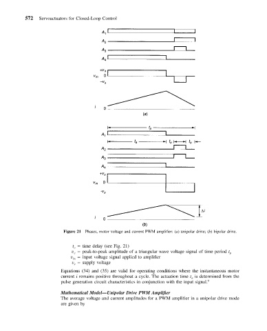
Figure 21 Phases, motor voltage and current PWM amplifier: (a) unipolar drive; (b) bipolar drive.
t time delay (see Fig. 21)
o
v peak-to-peak amplitude of a triangular wave voltage signal of time period t p
c
v input voltage signal applied to amplifier
in
v supply voltage
s
Equations (34) and (35) are valid for operating conditions where the instantaneous motor
current i remains positive throughout a cycle. The actuation time t is determined from the
a
pulse generation circuit characteristics in conjunction with the input signal. 9
Mathematical Model—Unipolar Drive PWM Amplifier
The average voltage and current amplitudes for a PWM amplifier in a unipolar drive mode
are given by