
Page 579 - Mechanical Engineers' Handbook (Volume 2)
P. 579
570 Servoactuators for Closed-Loop Control
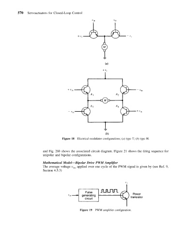
Figure 18 Electrical modulator configurations; (a) type T; (b) type H.
and Fig. 20b shows the associated circuit diagram. Figure 21 shows the firing sequence for
unipolar and bipolar configurations.
Mathematical Model—Bipolar Drive PWM Amplifier
The average voltage v ma applied over one cycle of the PWM signal is given by (see Ref. 9,
Section 4.5.3)
Figure 19 PWM amplifier configuration.