Page 606 - Mechanical Engineers' Handbook (Volume 2)
P. 606

10 Steady-State and Dynamic Behavior of Servoactuators and Servosystems  597


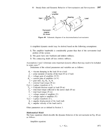
                                      Figure 40 Schematic diagram of an electromechanical servoactuator.


                              A simplified dynamic model may be derived based on the following assumptions:
                              1. The amplifier bandwidth is considerably greater than that of the servomotor load
                                 portion of the system.
                              2. The gears have zero backlash and infinite stiffness.
                              3. The connecting shafts all have infinite stiffness.

                           Assumptions 2 and 3 eliminate some important dynamic effects that may need to be included
                           in some cases. 41
                              Definitions of the critical parameters and variables are as follows:

                             B   viscous damping in the load (N m s/rad)
                              L
                             J   polar moment of inertia of the load (N m s /rad)
                                                                    2
                              L
                             K   voltage gain of amplifier (V/V)
                              a
                            K ac    current gain of amplifier (A/V)
                              n   gear ratio,   /  ,   /  L
                                               L
                                           m
                                                 m
                             T   external load torque (N m)
                              e
                           T (s)   Laplace transform of T d
                            d
                            T ƒL    Coulomb friction torque in load (N m)
                             T   total load torque reflected to the motor shaft (N m)
                              m
                             T   total load torque (N m)
                              L
                             v   voltage output of amplifier (V)
                              a
                             v   voltage input to amplifier (V)
                              i
                           V (s)   Laplace transform of v i
                            i
                                 angular displacement of the load (rad)
                              L
                                angular velocity of the load (rad/s)
                              L
                           Other parameters are as defined in Section 3.
                           Mathematical Model
                           The basic equations which describe the dynamic behavior of the servoactuator in Fig. 40 are
                           as follows:
                              Amplifier equation:
                                                           v   K v                              (67)
                                                                 a i
                                                            a
   601   602   603   604   605   606   607   608   609   610   611