Page 610 - Mechanical Engineers' Handbook (Volume 2)
P. 610
10 Steady-State and Dynamic Behavior of Servoactuators and Servosystems  601

                           Numerical Example
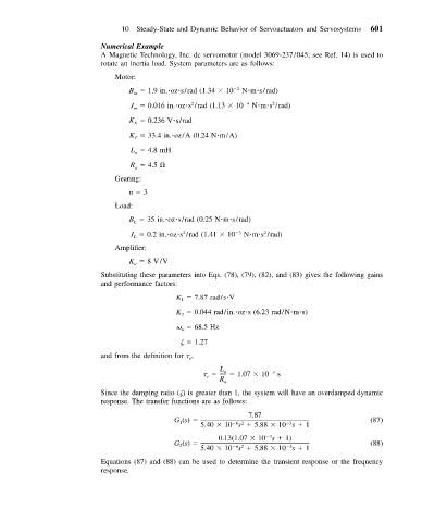
                           A Magnetic Technology, Inc. dc servomotor (model 3069-237/045; see Ref. 14) is used to
                           rotate an inertia load. System parameters are as follows:
                              Motor:
                                  B   1.9 in. oz s/rad (1.34   10  2  N m s/rad)
                                   m
                                                                       2
                                                  2
                                  J   0.016 in. oz s /rad (1.13   10  4  N m s /rad)
                                   m
                                  K   0.236 V s/rad
                                   E
                                  K   33.4 in. oz/A (0.24 N m/A)
                                   T
                                  L   4.8 mH
                                   a
                                  R   4.5
                                   a
                              Gearing:
                                  n   3
                              Load:
                                  B   35 in. oz s/rad (0.25 N m s/rad)
                                   L
                                                2
                                                                    2
                                  J   0.2 in. oz s /rad (1.41   10  3  N m s /rad)
                                   L
                              Amplifier:
                                  K   8 V/V
                                   a
                           Substituting these parameters into Eqs. (78), (79), (82), and (83) gives the following gains
                           and performance factors:
                                              K   7.87 rad/s V
                                               1
                                              K   0.044 rad/in. oz s (6.23 rad/N m s)
                                               2
                                                  68.5 Hz
                                               n
                                                   1.27
                           and from the definition for   ,
                                                 e
                                                          L a    1.07   10  3  s
                                                      e
                                                         R a
                           Since the damping ratio ( ) is greater than 1, the system will have an overdamped dynamic
                           response. The transfer functions are as follows:
                                                                7.87
                                              G (s)                                             (87)
                                               1
                                                             62
                                                                           3
                                                    5.40   10 s   5.88   10 s   1
                                                                      3
                                                         0.13(1.07   10 s   1)
                                              G (s)                                             (88)
                                               2
                                                                           3
                                                             62
                                                    5.40   10 s   5.88   10 s   1
                           Equations (87) and (88) can be used to determine the transient response or the frequency
                           response.

