
Page 613 - Mechanical Engineers' Handbook (Volume 2)
P. 613
604 Servoactuators for Closed-Loop Control
Numerical Example
Consider a closed-loop electromechanical servosystem comprising the open-loop system of
Section 10.1 with velocity feedback added. For the same numerical values as in the numerical
example of Sec. 10.1 and with K 3 V/krpm, the following results are obtained.
f
K 6.42 rad/s V
3
K 0.036 rad/in. oz s (5.10 rad/N m s)
4
n1 75.8 Hz
1.143
1
10.3 Electrohydraulic Servoactuators
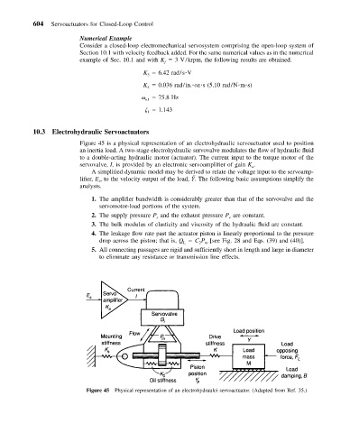
Figure 45 is a physical representation of an electrohydraulic servoactuator used to position
an inertia load. A two-stage electrohydraulic servovalve modulates the flow of hydraulic fluid
to a double-acting hydraulic motor (actuator). The current input to the torque motor of the
servovalve, I, is provided by an electronic servoamplifier of gain K .
a
A simplified dynamic model may be derived to relate the voltage input to the servoamp-
lifier, E , to the velocity output of the load, Y ˝ . The following basic assumptions simplify the
s
analysis.
1. The amplifier bandwidth is considerably greater than that of the servovalve and the
servomotor-load portions of the system.
2. The supply pressure P and the exhaust pressure P are constant.
e
s
3. The bulk modulus of elasticity and viscosity of the hydraulic fluid are constant.
4. The leakage flow rate past the actuator piston is linearly proportional to the pressure
drop across the piston; that is, Q C P [see Fig. 28 and Eqs. (39) and (40)].
2
L
m
5. All connecting passages are rigid and sufficiently short in length and large in diameter
to eliminate any resistance or transmission line effects.
Figure 45 Physical representation of an electrohydraulci servoactuator. (Adapted from Ref. 35.)