Page 614 - Mechanical Engineers' Handbook (Volume 2)
P. 614

10 Steady-State and Dynamic Behavior of Servoactuators and Servosystems  605

                              6. The mass of the moving parts in the servomotor (M ) and the viscous damping in
                                                                           a
                                 the servomotor (B ) are small compared to the mass (M) and the viscous damping
                                               m
                                 (B) associated with the load.
                              7. The Coulomb friction and stiction forces in the servomotor and load are negligible.
                           Mathematical Model
                           The typical servoamplifier is governed by the equation
                                                           I   KE                              (103)
                                                                as
                           Equation (61) describes the steady-state behavior of the electrohydraulic servovalve. This
                           equation can be used in the dynamic analysis of the servoactuator if the servovalve dynamics
                           are negligible compared to the servomotor-load dynamics. Otherwise, either Eq. (65) or (66)
                           should be used. Equations (38)–(44) describe the dynamic behavior of the servomotor. The
                           external load force in Eq. (38) may be expressed as follows:
                                                          dY      dY
                                                            2
                                               F   F   M        B     K(Y   Y)                 (104)
                                                     L
                                                e
                                                                         p
                                                           dt 2   dt
                              The set of algebraic equations outlined above cannot be combined into a single dynamic
                           equation or transfer function because of nonlinearities. Also, since the set of equations is
                           rather complex, conclusions about the performance of the system cannot be drawn without
                           actually solving the equations for a variety of conditions. A computer-based analysis is the
                           only practical method of determining the steady-state and dynamic performance of the system
                           unless the equations are linearized in some fashion.
                              A linearized model which assumes small perturbations of all variables about an initial
                           steady-state operating condition can be very useful in quickly assessing system dynamic
                           behavior. Such a model is particularly useful for preliminary design and as a reference when
                           an analysis is made using the set of nonlinear describing equations.
                              It can be shown 45  that for the case when V   V   V (see Fig. 28) and under the
                                                                 1i
                                                                      2i
                                                                            i
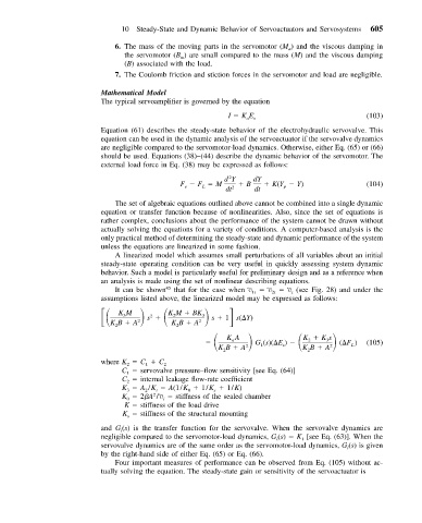
                           assumptions listed above, the linearized model may be expressed as follows:
                               KM      s       KM   BK 3
                                             2
                                 3
                                       2
                             KB   A 2        K B   A 2  s   1 s(	Y)
                                              2
                              2
                                                           KA     G (s)(	E )    K   Ks
                                                            a
                                                                                2
                                                                                    3
                                                                                           L
                                                         KB   A 2   1    s    K B   A 2  (	F )  (105)
                                                          2                     2
                           where K   C   C 2
                                      1
                                 2
                                C   servovalve pressure–flow sensitivity [see Eq. (64)]
                                 1
                                C   internal leakage flow-rate coefficient
                                 2
                                K   A /K   A(1/K   1/K   1/K)
                                                        s
                                 3
                                         t
                                                 0
                                      2
                                        2
                                K   2 A /V   stiffness of the sealed chamber
                                           i
                                 0
                                 K   stiffness of the load drive
                                K   stiffness of the structural mounting
                                  s
                                (s) is the transfer function for the servovalve. When the servovalve dynamics are
                           and G i
                           negligible compared to the servomotor-load dynamics, G (s)   K [see Eq. (63)]. When the
                                                                              1
                                                                        i
                           servovalve dynamics are of the same order as the servomotor-load dynamics, G (s)is given
                                                                                          i
                           by the right-hand side of either Eq. (65) or Eq. (66).
                              Four important measures of performance can be observed from Eq. (105) without ac-
                           tually solving the equation. The steady-state gain or sensitivity of the servoactuator is
   609   610   611   612   613   614   615   616   617   618   619