Page 612 - Mechanical Engineers' Handbook (Volume 2)
P. 612
10 Steady-State and Dynamic Behavior of Servoactuators and Servosystems 603
KK
G (s) a T (93)
3
RB ( s 1)( s 1) KK KKK T
at
T
m
e
E
ƒ
a
(R /n)( s 1)
G (s) a e (94)
4
RB ( s 1)( s 1) KK KKK T
a
T
e
m
E
at
ƒ
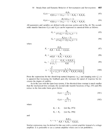
All parameters and variables are defined in the previous section and in Fig. 44. The second-
order transfer functions G (s) and G (s) can be expressed in canonical form as follows:
3
4
K
G 3 (95)
3
2
2
(s / ) (2 / )s 1
1
n1
n1
K ( s 1)
G 4 e (96)
4
2
2
(s / ) (2 / )s 1
n1 1 n1
where
KK
K a T (97)
3
RB KK KKK T
E
T
a
ƒ
at
R
K a (98)
4
n(RB KK KKK )
at
T
E
T
ƒ
a
1 1 KK KKK T
ƒ
T
a
E
n1 (99)
em RB t
a
1
e m (100)
1
2
[1 (KK KKK )/RB ]
em T E ƒ a T a t
From the expressions for the closed-loop natural frequency ( ) and damping ratio ( ), it
n1
1
is apparent that increasing the feedback gain (K ) increases the speed of response but de-
f
creases the degree of stability.
As in the case with the open-loop system, if the electrical time constant is much smaller
than the mechanical time constant, the second-order transfer functions of Eqs. (95) and (96)
reduce to the first-order forms given below:
K
G (s) 5 (101)
5
s 1
5
K
G (s) 6 (102)
6
s 1
6
where
K K 3 [see Eq. (97)]
5
K K 4 [see Eq. (98)]
6
and
RB
ai m
6
5
RB KK KKK T
at
T
E
a
ƒ
Similar expressions may be derived for the case with a current amplifier instead of a voltage
amplifier. It is preferable to use a current amplifier where cost is not prohibitive.

