
Page 609 - Mechanical Engineers' Handbook (Volume 2)
P. 609
600 Servoactuators for Closed-Loop Control
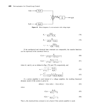
Figure 43 Block diagram of a servoactuator with voltage input.
KK
K a T (78)
1
RB KK E
T
at
R
K a (79)
2
n(RB KK )
E
at
T
RB
at m
1 2
RB KK E
at
T
If the mechanical and electrical time constants are comparable, the transfer functions
can be expressed in the canonical form as
K
G (s) 1 (80)
1
(s / ) (2 / )s 1
2
2
n
n
K ( s 1)
G (s) 2 e (81)
2
2
2
(s / ) (2 / )s 1
n n
where K and K are as defined in Eqs. (78) and (79), respectively, and
2
1
1 1 KK
T
RB E t (82)
n
em
a
m
1
e
2 [1 (KK /RB )] (83)
T
em
E
a
t
If a current amplifier is used instead of a voltage amplifier, the resulting linearized
dynamic model of the system is given by
m(s) G (s) I(s) G (s) T (s) (84)
e
4
3
where
KK
G (s) T ac (85)
3
B ( s 1)
t
m
1
G (s) (86)
4
Bn( s 1)
t
m
That is, the electrical time constant is not a factor if the current amplifier is used.