
Page 631 - Mechanical Engineers' Handbook (Volume 2)
P. 631
622 Controller Design
disturbance. Anomalies in the actuator and load must also be offset by a finite error signal.
Examples are temperature-induced null shifts, hysteresis, threshold, friction, and lost motion.
The magnitude of these error signals is minimized if the amplifier gain is high.
Ideally, the amplifier gain would be set high enough that the accuracy of the servo
becomes dependent only upon the accuracy of the transducer itself. In practice, however, the
amplifier gain is limited by stability considerations. Therefore, it is desirable to provide high
gains at low frequencies for accuracy and low gains at high frequencies to minimize stability
problems. Since the rate of amplitude roll-off with frequency is directly related to phase lag,
excessive roll-off can create more stability problems than it solves. A good compromise is
to make the entire forward path look like an integrator over the frequency range of interest
(a type I system). This technique is very commonly used to give nearly infinite static gain
and a linear gain roll-off with frequency, at the cost of 90 phase lag.
It is important to note that some servoloops contain an inherent integrator, which com-
plicates the accuracy-versus-stability problem. For example, many actuators are inherently
rate devices when operated open loop, so that a steady input results in a proportional velocity
output. A velocity servo using such an actuator will inherently have a proportional forward
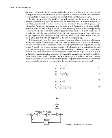
loop, and an integrating servoamplifier can be used (Fig. 2). However, the corresponding
position servo will inherently have an integration in the forward loop, as shown in Fig. 3.
In this latter case, the use of an integrating servoamplifier can cause severe stability problems.
From these figures, transfer functions can be written for the closed-loop responses to com-
mand and disturbance inputs. Note that the dynamic response characteristics of all elements
have been neglected, and it is assumed that the load includes no spring to ground:
V 1 1
(1)
e c K s/K vv 1
v
V s
K (2)
F d 4 s K vv
X 1 1
(3)
e K s/K 1
c x vx
X K 1
4 (4)
vx
vx
F d K s/K 1
Figure 2 Simplified velocity servo.