
Page 636 - Mechanical Engineers' Handbook (Volume 2)
P. 636
2 Fundamentals of Closed-Loop Performance 627
the closed-loop transfer function consists of a first-order and a second-order lag. The break
frequency of the first-order lag increases with 1oop gain, while the second-order damping
ratio rapidly decreases. In both loop closures, there are clearly trade-offs between closed-
loop bandwidth and stability.
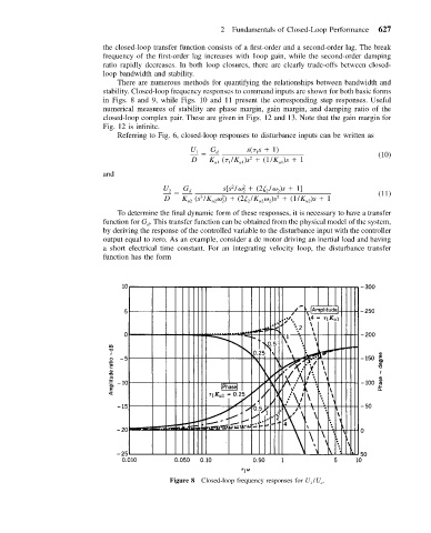
There are numerous methods for quantifying the relationships between bandwidth and
stability. Closed-loop frequency responses to command inputs are shown for both basic forms
in Figs. 8 and 9, while Figs. 10 and 11 present the corresponding step responses. Useful
numerical measures of stability are phase margin, gain margin, and damping ratio of the
closed-loop complex pair. These are given in Figs. 12 and 13. Note that the gain margin for
Fig. 12 is infinite.
Referring to Fig. 6, closed-loop responses to disturbance inputs can be written as
U 1 G d s( s 1) (10)
1
2
D K ( /K )s (1/K )s 1
u1 1 u1 u1
and
2
2
U G s[s / (2 / )s 1]
2 d 2 2 2 (11)
3
2
D K (s /K ) (2 /K )s (1/K )s 1
2
2
u22
u2
u2
u22
To determine the final dynamic form of these responses, it is necessary to have a transfer
function for G . This transfer function can be obtained from the physical model of the system,
d
by deriving the response of the controlled variable to the disturbance input with the controller
output equal to zero. As an example, consider a dc motor driving an inertial load and having
a short electrical time constant. For an integrating velocity loop, the disturbance transfer
function has the form
Figure 8 Closed-loop frequency responses for U 1 /U c .