Page 654 - Mechanical Engineers' Handbook (Volume 2)
P. 654
4 Inner Feedback Loops  645

                           case, loop gains selected to obtain adequate performance and stability from the dominant
                           low-frequency modes could be high enough to drive the poorly damped high-frequency
                           modes unstable. This is particularly likely if lead compensation is used to improve the
                           dynamics of the dominant modes. High-frequency stability is probably best assessed by a
                           root-locus plot or Bode plot that includes estimates of all the system dynamic modes. Often,
                           accurate description of the higher order modes is difficult at the design stage. For this reason,
                           it is worthwhile investigating the effects of various high-frequency compensation techniques
                           that can be added when the system is first evaluated experimentally. For example, notch
                           filters are often useful in reducing the effects of high-frequency structural modes at the cost
                           of some low-frequency phase lag.
                              Many higher order modes are reasonably well damped. The dynamics of drive ampli-
                           fiers, transducer signal conditioners, and notch filters are typical examples. The primary
                           influence of such modes is that they introduce phase lags that can destabilize the low-
                           frequency dominant modes or limit the effectiveness of lead compensation used to improve
                           low-frequency behavior. A useful approximation of these effects can be made if there is
                           reasonable frequency separation of the higher order modes from the dominant lower fre-
                           quency modes (a factor of 5 or more). In this case, the system’s low-frequency dynamic
                           behavior can usually be assessed by replacing the high-frequency modes with a single first-
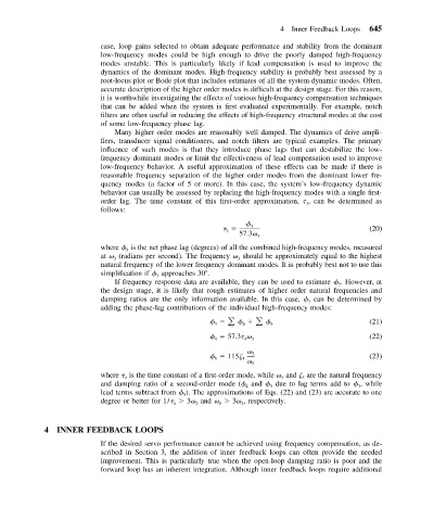
                           order lag. The time constant of this first-order approximation,   , can be determined as
                                                                               3
                           follows:

                                                                 3                              (20)
                                                           3
                                                              57.3
                                                                   3
                           where   is the net phase lag (degrees) of all the combined high-frequency modes, measured
                                 3
                           at   (radians per second). The frequency   should be approximately equal to the highest
                              3
                                                              3
                           natural frequency of the lower frequency dominant modes. It is probably best not to use this
                           simplification if   approaches 30 .
                                         3
                              If frequency response data are available, they can be used to estimate   . However, at
                                                                                        3
                           the design stage, it is likely that rough estimates of higher order natural frequencies and
                           damping ratios are the only information available. In this case,   can be determined by
                                                                                3
                           adding the phase-lag contributions of the individual high-frequency modes:
                                                                       5                        (21)
                                                        3
                                                               4
                                                           57.3   3                             (22)
                                                        4
                                                                4

                                                           115  5  3                            (23)
                                                        5
                                                                  5
                           where   is the time constant of a first-order mode, while   and   are the natural frequency
                                 4                                       5    5
                           and damping ratio of a second-order mode (  and   due to lag terms add to   , while
                                                                4     5                      3
                           lead terms subtract from   ). The approximations of Eqs. (22) and (23) are accurate to one
                                                3
                           degree or better for 1/    3  and     3  , respectively.
                                             4     3     5     3
            4 INNER FEEDBACK LOOPS
                           If the desired servo performance cannot be achieved using frequency compensation, as de-
                           scribed in Section 3, the addition of inner feedback loops can often provide the needed
                           improvement. This is particularly true when the open-loop damping ratio is poor and the
                           forward loop has an inherent integration. Although inner feedback loops require additional

