
Page 796 - Mechanical Engineers' Handbook (Volume 2)
P. 796
6 Observer-Based Controllers 787
the resulting system has satisfactory performance. This stage of the design therefore requires
considerable trial and error.
36
Athans has suggested using the steady-state Kalman–Bucy filter formulation with sta-
tionary system and noise characteristics. It should be noted, however, that the formulation
is not used here to perform an estimation task. It is being used here to help calculate the
matrix L because the resulting target feedback loop has well-known performance and ro-
36
bustness characteristics. At the minimum, selection of L as described by Athans guarantees
that the target feedback loop will not amplify disturbances entering the system at the output.
In addition, the target feedback 1oop will not go unstable as long as the modeling uncertainty
e ( ) in Eq. (122) is below 0.5.
m
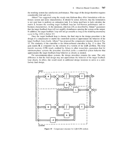
Once the target feedback loop is chosen, the final step in the design procedure is the
design of a compensator to enable the controlled system to approximate the behavior of the
target feedback loop closely. Athans has proposed the compensator structure shown in Fig.
36
15. The similarity of the controller to the observer-based controller in Fig. 12 is clear. The
gain matrix K is computed via the solution of a version of the LQR problem. The loop
transfer recovery (LTR) result, credited by Athans to other researchers, guarantees that for
minimum-phase systems the procedure described yields a controlled system behavior that
approximates the target feedback loop behavior as closely as desired.
For non-minimum-phase systems, the design procedure remains the same. The only
difference is that the final design may not approximate the behavior of the target feedback
loop closely. In effect, this would result in additional design iterations to arrive at a satis-
factory final design.
Figure 15 Compensator structure for LQR/LTR method.