Page 846 - Mechanical Engineers' Handbook (Volume 2)
P. 846

1 Basic Analog Electronics  837

                                                                           Time response
                                             V
                                          –     +                       i(t)
                                                    t = 0
                                                                       V

                                                                       R
                                      R        i       L
                                                                                      t
                                                Figure 20 An RL circuit (see Eq. 18b).


                                             V                             Time response
                                           –    +
                                                    t = 0               i(t)
                                                                       V
                                       R       i       L               R
                                                                                      t
                                                Figure 21 An RL circuit (see Eq. 19b).


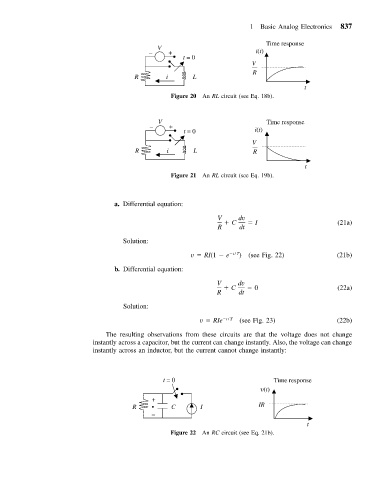
                                 a. Differential equation:
                                                             V     dv
                                                                 C      I                      (21a)
                                                             R     dt
                                   Solution:

                                                      v   RI(1   e  t / T )  (see Fig. 22)     (21b)
                                 b. Differential equation:

                                                             V     dv
                                                                 C      0                      (22a)
                                                             R     dt
                                   Solution:
                                                         v   RIe  t / T  (see Fig. 23)         (22b)

                              The resulting observations from these circuits are that the voltage does not change
                           instantly across a capacitor, but the current can change instantly. Also, the voltage can change
                           instantly across an inductor, but the current cannot change instantly:


                                                 t = 0                       Time response
                                                                           (t)
                                           +
                                      R    •     C       I               IR
                                           –
                                                                                      t
                                                Figure 22 An RC circuit (see Eq. 21b).
   841   842   843   844   845   846   847   848   849   850   851