Page 847 - Mechanical Engineers' Handbook (Volume 2)
P. 847

838   Mechatronics

                                                                             Time response
                                            t = 0
                                                                           (t)
                                         +
                                    R    •     C       I                IR
                                         –
                                                                                      t
                                               Figure 23 An RC circuit (see Eq. 22b).


                                                             V      I
                                                       C    No     Yes
                                                       L    Yes    No

                             The instantaneous behavior (t is small) steady-state behavior (t is large) is also inter-
                          esting. This shows that a capacitor begins like a short circuit and becomes an open circuit.
                          Also, an inductor begins as an open circuit and becomes a short circuit:
                                                          Capacitor    Inductor

                                               t   0        Short       Open
                                               t            Open        Short


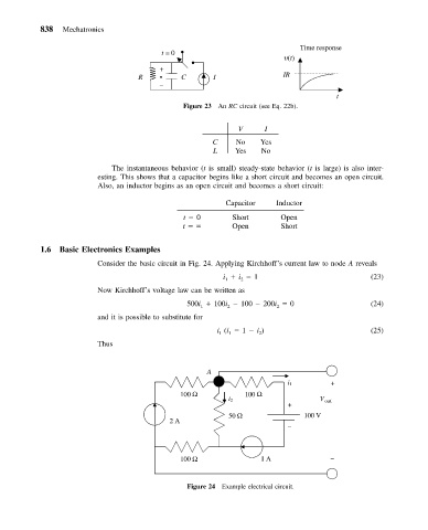
           1.6  Basic Electronics Examples
                          Consider the basic circuit in Fig. 24. Applying Kirchhoff’s current law to node A reveals
                                                         i   i   1                            (23)
                                                          1
                                                              2
                          Now Kirchhoff’s voltage law can be written as
                                                500i   100i   100   200i   0                  (24)
                                                                       2
                                                          2
                                                    1
                          and it is possible to substitute for
                                                        i (i   1   i )                        (25)
                                                        1
                                                           1
                                                                  2
                          Thus
                                                     A
                                                                         i 1        +
                                              100 Ω            100 Ω
                                                           i 2                    V out
                                                                          +
                                                           50 Ω               100 V
                                            2 A
                                                                          –


                                              100 Ω                1 A              –


                                                Figure 24 Example electrical circuit.
   842   843   844   845   846   847   848   849   850   851   852